The Randall Museum in San Francisco hosts a large HO-scale model railroad. Created by the Golden Gate Model Railroad Club starting in 1961, the layout was donated to the Museum in 2015. Since then I have started automatizing trains running on the layout. I am also the model railroad maintainer. This blog describes various updates on the Randall Museum Model Railroad and I maintain a separate tech blog for all my electronics & software not directly related to Randall.
2017-01-04 - NCE Button Board
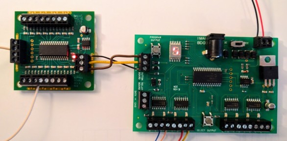
Category RandallAfter talking to tech support at NCE: the Button Board has a bug and they don't support non-momentary switches like the rotary toggles we use. It MUST be momentary.
<cold shower>
Proposed hack to verify: add a push button on the common ground of leading to the rotary toggles. Operation mode is thus turn a toggle then push the button to simulate a momentary push.
Longer term: my first reaction is to just simulate the Button Board using an Arduino. Must take 16 digital inputs and emit the proper 2-bytes sequence over serial.
Or realize that the Button Board uses a PIC16. It’s no different from an Arduino and I can reprogram it.
Uses PIC16F1936, 28 pin package.
Datasheet: http://ww1.microchip.com/downloads/en/DeviceDoc/41364E.pdf
The board has a 6-holes "headers" which should be the PIC16's ICSP (In-Circuit Serial Programming, chapter 28, page 361). The 6 pins, from left to right, when holding the PIC16 with 1 at the top-left:
- 1 = Pin 1 (Vpp / !MCLR)
- 2 = Header 1 with a 10k resistor to Pin 20 (Vdd)
- 3 = GND / Pin 8 (Vss)
- 4 = Pin 28 (ICSPDATA)
- 5 = Pin 27 (ICSPCLK)
- 6 = Not Connected
Note: Vss is the ground ref, Vdd is the positive supply, Vpp is the programming voltage.
Vdd max is +5.5V and Vpp max is +9V.
There's something called a "Pickit2" to easily connect and program using directly that connector.
Another option is to use an Arduino as a PIC programmer.
⇒ Must use a PicKit3 for this version of the PIC16F.
The PIC16F I/Os are used as such:
RA0 = Turnout 1 N RA1 = Turnout 1 R RA2 = Turnout 2 N RA3 = Turnout 2 R RA4 = Turnout 3 N RA5 = Turnout 3 R RA7 = Turnout 4 R RA6 = Turnout 4 N |
RB0 = Turnout 5 N RB1 = Turnout 5 R RB2 = Turnout 6 N RB3 = Turnout 6 R RB4 = Turnout 7 N RB5 = Turnout 7 R RB6 / ICSPCLK = ICSP Pin 5 -- don't use RB7 / ICSPDATA = ICSP Pin 4 -- don't use |
RC0 = Turnout 8 R RC1 = Turnout 8 N RC2 = Not connected? RC3 = Onboard LED via resistor RC4 = Not connected? RC5 = Not connected? RC6 / TX = DATA via resistor RC7 / RX = Shunted to RC6 |
I didn't see anything obvious used for RC2, RC4 and RC5.
It's quite odd that RC6 (TX) and RC7 (RX) are connected together to the DATA pin of the terminal block.
MPLAB X : can read from the device but only shows zeroes. Does not dissemble.
MPLAB 8 : connects to the PicKit3 but fails to read from it. Indicates "Target ID" is 0x0000.
I think they used the read-protection (to avoid exactly what I’m doing; I’m not blaming them, I’d do the same if I were running a business), so I can reflash the whole thing but I can’t just get the existing program and disassemble it. Tried to ask nicely for the source to NCE but that went to /dev/null...