The Randall Museum in San Francisco hosts a large HO-scale model railroad. Created by the Golden Gate Model Railroad Club starting in 1961, the layout was donated to the Museum in 2015. Since then I have started automatizing trains running on the layout. I am also the model railroad maintainer. This blog describes various updates on the Randall Museum Model Railroad and I maintain a separate tech blog for all my electronics & software not directly related to Randall.
2018-01-12 - Sonora Signal Mast
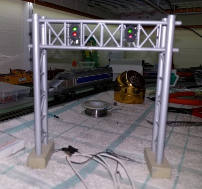
Category RandallThe signal mast on Sonora is a double track signal bridge.
What we want, for trains going up hill:
- T330 Normal aka “mainline” (block 320). Mainline green, Siding red.
- T330 Reversed aka “siding” (block 321). Mainline red, Siding green.
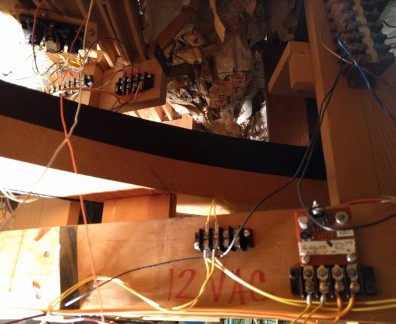
First I need to identify wires under the layout, there are likely 6 of them, 3 for each signal.
Apparently most of these use a common anode (e.g. http://www.sbsignal.com/ho-signals-and-systems.html).
[Update ⇒ 5, one is a common anode.]

Let’s say one common anode (aka positive, goes to + DC) and 2 cathode ("negatives").
Anode = +, Cathode = -.
Using a 1.5V battery, find 2 wires that light up one led. + is anode. If - on the 3rd wire lights the other led, that + side is a common anode.
Obviously that test implies all the LEDs are still working :-/
[Update ⇒ they were dead. Replaced them.]
We can wire the double track signal either using a DC/AC bus + Tortoise, or using the DCC rail polarity from the frog. Let’s call A the rail on the frog side, and B the continuous “outside” rail.
Turnout |
Frog |
Green Main |
Red Main |
Green Siding |
Red Siding |
Normal Main |
Rail A |
Frog-B = on |
Frog-A = off |
Frog-A = off |
Frog-B = on |
Reverse Siding |
Rail B |
Frog-B = off |
Frog-A = on |
Frog-A = on |
Frog-B = off |
For each signal, the common anode is connected to the frog. Each led cathode is connected to the rail A or B using a resistor, say 1k-10k depending on brightness.
Alternatively we can simplify wiring by using only one resistor per common anode, whichever is simpler to wire under the layout.
Typical red/green LED Vf is 1.8-2 V, 20 mA max.
Let’s say DCC = 12 V peak to peak; 12-2=10 V; 10 V / 10 mA = 1k Ω; 10 V / 20 mA = 500 Ω;