The Randall Museum in San Francisco hosts a large HO-scale model railroad. Created by the Golden Gate Model Railroad Club starting in 1961, the layout was donated to the Museum in 2015. Since then I have started automatizing trains running on the layout. I am also the model railroad maintainer. This blog describes various updates on the Randall Museum Model Railroad and I maintain a separate tech blog for all my electronics & software not directly related to Randall.
2018-11-22 - More Automated Routes
Category RandallBased on last week's experimentation at Randall, here are a few more ideas of automated routes, with a focus on what would be needed to make them happen. To be clear, none of this will happen any time soon, or even at all.
1- Trolley

Jim got this little trolley a while -- it is the Atlantic City from Bowser streetcar. We’re not using it yet and I can see two automation options:
A- On the small spur of the SIA that is directly behind the stockton “city”. Technically that spur was probably created to serve “local industries” and the end of the line ends up inside some kind of industrial building. However it’s right behind the city, and viewed from the front could be an interesting visual option seeing the trolley going back and forth behind the buildings.
Also interesting that this spur is typically not used and pretty much isolated so it can be dedicated to this purpose only.
Requirements:
- Some kind of way to detect both ends / or location of the trolley on the spur. E.g. camera, reflective IR (side mounted or on end bumper could work there, see warning note at the end), or create additional blocks (cut 1 rail, add feeder + BD20, one each end).
- Add end bumpers if not present as there is no “overshoot” space.
- Bumpers can be mixed with a contact or a reflective IR detector, so they both act as stoppers too.
- Optional: DCC turnout control/interlock to prevent it from being thrown.
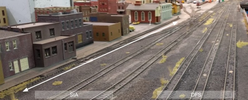
B- A longer trolley path from the SIA/branchline main track, for example from the SIA/DFS/RH junction up to the branchline tunnel.
One nice thing about it is having a train “hide” in the branchline tunnel and regularly emerge via the little bridge. That adds some nice variety.
Requirements / issues:
- This is a potentially usable path, so a way to stop & park the automation out of the way is needed.
- This route crosses several booster boundaries. Notably it triggers the branchline reverser, which may or may not have an impact on the BL automation.
- Momentum + current keeper needed to ensure the train goes through the blocks properly.
- Block detectors could likely be used here: one in the tunnel, two on the SIA side (one stop block + one overshoot block).
- Optional: DCC turnout control/interlock.
C- A mix of A & B. A train could emerge from the branchline tunnel, cross the SIA, enter the spur next to the city and end up under that industrial building.
Option A is the easiest of the 3 to implement. Option B could be a different automation in its own with a short freight train coming out of the branchline tunnel and stopping in the DFS or SIA yards.
2- Switcher in SIA
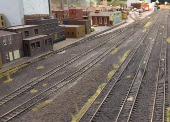
The SIA has all these yard tracks which are mostly unused. A “simple” idea is to have 1 or 2 switchers with attached freight cars. Switchers can pull out of a yard track into a spur/interchange, then push back into another yard track. Even more interesting with 2 switchers.
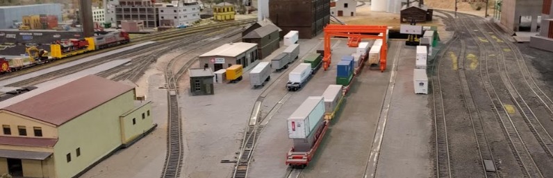
A couple years ago, I wanted to do an automated Inglenook Sidings puzzle solver (with, ahem, OpenCV and camera detection of the cars & their location). At the same time Jim wanted an automation with a switcher automatically shuttling freight cars. I actually started building one at home and I put the project aside as I got busy with Randall’s more mundane tasks. However here I would put Jim’s idea of coupling/uncoupling freight cars automatically aside as it proved unreliable or at least extremely finicky, and that’s not something I want for daily automation. Instead we can have for example 2 switchers with 2-3 freight cars each, in a fixed setup. The program could randomize which train leaves a yard track and which yard track it goes into. If that can be made reliable enough, I’d totally give another look at the automatic coupling issue (actually “uncoupling” reliably on magnets was the actual hard part).
The engines would be “pushing” the freight cars into the yard tracks. This means we can use an electrical block detector on the yard track feeder to know when the engine is there. We do have to make sure the engine clears the turnout.
When pulling into the spur/interchange track, the engine would be leading. Here we need more than just block detection, we need point detection. We can use something like a side-mounted reflective IR to know when to stop the engine at the end of the spur, but in this case we need to take into account the warning about the polling speed impact on the IR sensors.
Requirements:
- Ability to stop the automation.
- Block detectors for each yard track. Since the engines would likely be pushing the freight
- Detector for end of spur/interchange. E.g. reflective IR.
- Required turnout control for each yard track. Here these are twin-coils, so an NCE Q-Snap (4 turnouts) would be needed.
3- Switcher in DFS yard
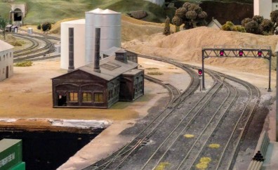
A similar automation could be done in the DFS yard. It has 3 tracks, however it is long enough and far away enough that a train moving from one track to the other would not offer enough visual difference to be noticeable from the public point of view, and that’s a primordial factor. In that case a simpler automation and similar to case 1-A above is to have a train hide in the branchline tunnel, come out of it, and stop in the DFS yard.
Requirements:
- Ability to stop the automation.
- Block detectors for one yard track (should probably wire them all if possible).
- Block detector to stop in the branchline tunnel.
- Optional: Block detectors for segments in between (to track progress).
- Required turnout control to enter that yard track (at least one Tortoise turnout if using the first DFS track).
A note on the limitation of sensors
In this kind of automation, time response becomes critical.
The current NCE AIU01 setup does not offer a very timely response time as the NCE cab bus sampling rate seems rather appalling. With this, we can expect response times in seconds. The Conductor software operates at 30 Hz but it can only act once it got a sensor input.
This has a direct impact on the design, e.g. if either a BD20 or IR is connected to an AIU01, it needs to stay on long enough for it to trigger the Conductor condition. At slow speed the BD20 can “flicker” and always be sampled as unoccupied. The IR sensor may not trigger long enough to be polled as occupied by the AIU01 either.
I had a similar issue with the green activation buttons connected to the AIU01 at first. Short pushes of the buttons were sometimes undetected. In that case the solution was to add a resistor + capacitor to the button, taking advantage of the pull-up nature of the AIU01 input.
The IR case can be solved by external circuitry -- e.g. an NE555 added to the IR sensor to make sure it stays on long enough to be detected. The trick with the capacitor is not enough with the IR sensor as its logic is inverted.
Another option is to bypass the NCE cab bus altogether. For example a Digitrax Loconet should not have the sample rate issue of the NCE cab bus [citation needed].
Another option is to use an arduino to drive the IR sensors, with either ethernet wired or wifi. In this case, we can reverse the mechanism -- instead of Conductor polling the sensor, we can directly have the arduino set virtual sensors in JMRI via the JSON server. I did not want to use this on the mainline automation as it means one more component that can fail for the main automation, nor did I want it to rely too much on “DIY” custom-made hardware. However these are secondary automations, fairly isolated. It is more acceptable for them to be offline for longer times if they fail.
Another option is to not use physical sensors at all and rely on camera vision -- notably IR cameras to be able to deal with variations in ambient light -- or structured-light sensors. The problem with this approach is the field of view available, based on camera placement. For example the spur described for the trolley in (1)-A could be covered by one camera, but placement would need to be very specific on the ceiling at a specific angle to detect the trolley under the covered building, et also avoid potential operators using the RH or SIA obscuring the view. Another camera could cover the SIA yard described in (2) for the switcher, but may not cover the spur needed to interchange between tracks. For a longer route like the long DFS yard and the branchline tunnel, camera options do not seem very practical.