The Randall Museum in San Francisco hosts a large HO-scale model railroad. Created by the Golden Gate Model Railroad Club starting in 1961, the layout was donated to the Museum in 2015. Since then I have started automatizing trains running on the layout. I am also the model railroad maintainer. This blog describes various updates on the Randall Museum Model Railroad and I maintain a separate tech blog for all my electronics & software not directly related to Randall.
2019-02-10 - Fairfield Industrial Yard
Category RandallRight in the middle of the layout is a fairly large industrial city. When visitors walk in, it’s right in the middle visible above the Mountain Panels.
When I discovered the layout back in 2014, this part of the layout was not powered, and it is still not functional today. I had started looking at it back in 2015 and realized there would be quite some work involved in making it fully functional (as in “tedious but not impossible”). But does it need to be fully functional? Since the layout runs as an “automated exhibit” now 4 days a week, I just realized this area has some great potential for some simple but effective automation even within its current state, and that would add great value to the visitors.
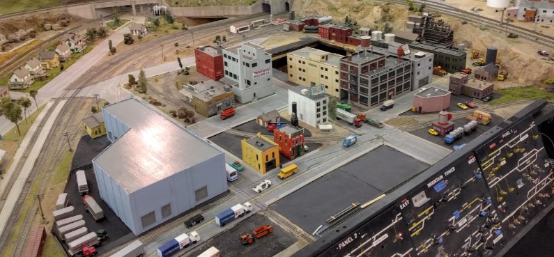
This represents the industrial park of the Fairfield, California and includes a good portion of street running. I am not sure what year this represents. This was designed for switching. There’s a dedicated control panel in front of it (see below).
The track plan:
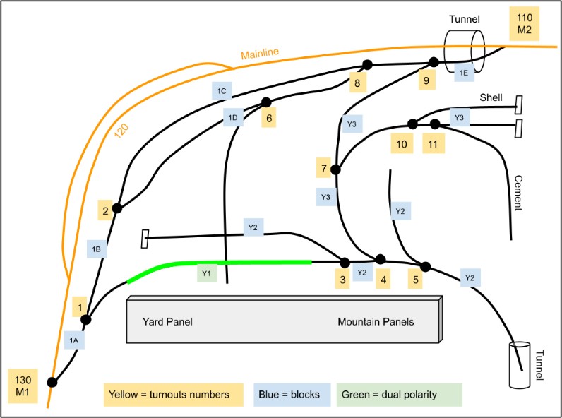
Blue labels on the track plan denote individually powered blocks. This was wired for DC and the green “Y1” section has polarity inversion which needs to be adjusted based on the state of the turnouts T1 and T4 (you can see that T1 - T4 - T9 form a delta Δ reversing loop).
The first track is nicely split in blocks: 1A, 1B, 1C, 1D and 1E.
The inner tracks are split in 3 blocks: Y1 is the reversing part, and Y2 and Y3 have different polarities.
The panel has a toggle to align Y1 either on the polarity of 1A or the one of Y3.
When trying under DCC, depending on the position of T4, I remember seeing either a short on the T3-T4 side or one of the T4-T5 side. Back in 2015 I did not quite manage to understand how that section was wired as a lot of the track feeder wiring is embedded in the sub-plywood.
In the blocks Y2 and Y3, a lot of the continuity seems to happen through the frog contact on the rails with no track feeders.
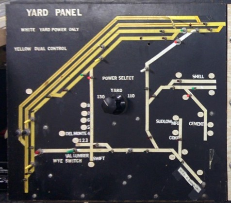
On the panel, the two first tracks in yellow at the very left with the barely-visible red line represent the mainline (block 120) and the Fairfield station siding (block 121). These blocks are controlled from the Valley Panel on the other side of the layout. The next two tracks in yellow are part of the yard and form a dedicated block.
Since this was designed for DC, the panel has a power selector to draw power from block 130 (turnout M1), or from block 110 (turnout M2), or from an internal power supply (when not joined to the mainline).
All the turnouts had been unconnected when I started my examination -- when the layout was converted to DCC, the layout turnouts were switched from AC to DC, but since these were still the original AC-only twin coils they were simply left unconnected. I started by rewiring an AC bus to bring power to these twin coils, and then I proceeded on testing them. Some would not throw, and some would not bring the right frog polarity:
Turnout |
Turnout |
Frog Power |
Notes |
M1 |
Functional |
2015: Functional 2017: Not functional. |
2015: Was functional. Suggested adding a Seize / Release on the valley panel with light status. 2017: Frog wired to normal (was being resistive and stopping some decoders). |
M2 |
Not connected? |
No idea |
Seize / Release with light status would be required to avoid mishaps. |
1 |
Mostly OK |
Functional |
The board holding the twin-coil is loose, needs to be screwed properly. |
2 |
Gap, needs work |
Loose, needs work |
Above: Curved closure rail doesn't fully close the gap. |
Under: the bar that makes the frog contacts is loose and sometimes creates a short. |
|||
3 |
Doesn't always snap |
Shorts when thrown |
Sometimes stuck and doesn't always snap towards the siding. |
Shorts when thrown towards siding (or that might be due to #4). |
|||
Power to siding seems to come from Y2 via the frog, turns off when switched [check] |
|||
4 |
Functional? |
Shorts + dead spot |
Shorts when thrown towards Y3. |
Dead spot between 4 and 5 on the upper rail. |
|||
5 |
Functional |
Functional |
Power to siding seems to come from Y2 via the frog, turns off when switched [check] |
6 |
No idea, must check |
No idea, must check |
Seems ok when going straight (between 2 and 8), didn't try switching yet. |
7 |
Functional |
Functional |
Both sides tested OK. |
8 |
Functional |
Functional |
Both sides tested OK. |
9 |
Buzz, doesn't switch |
No idea, must check |
Block 1E didn't seem powered, must check. |
10 |
Functional |
Functional |
Both sides tested OK. |
11 |
No idea, must check |
No idea, must check |
Was ok going straight, didn't try switching to the cement factory. |
Status Color: Green: work done here // Orange: functional but needs work // Red: not functional.
Suggestions:
- Install a separate DCC protection circuit so that shorts in the yard/city do not affect blocks 110 or 130.
- Remove the block selector (the round 130/Yard/110 knob) and instead use an on/off switch.
- Add a separate on/off switch for the turnouts AC with light indicator when powered.
- Replace the Y1 polarity inverter (green switch) by an automatic reverser (e.g. frog juicer) as used on DCC loops (and remove the reverser).
- Some of the small sidings seem powered by the frog. Not really an issue as long as it's understood.
Fully restoring this section of the layout is not very high on my current task list. The location makes it extremely hard to use for switching when public is present. However even in the current half-working state, it presents some interesting automation potential.
First let’s reduce the field to a known and manageable quantity:
- Let’s posit that the automation does not touch any turnout. They are placed in a fixed state. This simplifies a lot of things and avoids a lot of issues (especially when power routing is done via the turnout, never good for DCC block detection).
- Let’s posit we don’t use block detection in that case. Either infrared or some camera-based system is used.
- Let’s posit we use purely Y2 or Y3 blocks and “never cross the beams”.
Using these axioms, we can still do some basic shuttle-style automation:
- A small trolley can get out of the tunnel on the right bottom side and go up Y2 via T5. This stays on Y2.
- A small switcher with maybe one car could travel on Y3 via T7 and T10 or T11. There would be very small visual enhancement by trying to throw T10 or T11 to create some variety in the route, but it’s a substantial technical effort and may result only in minor subtle changes that most people may not notice; I’ll elaborate on that below.
- There’s some potential running on 1A-1E also in a shuttle manner with another switcher or similar.
- A better potential would be going from 1E to T8 / T6 and up to the Y1 crossing then shuttle back.
I’d call that “phase 1”: These are very simple linear routes, which could operate on a simple timer with the usual motion-activation trigger used elsewhere. Actual control could be done locally using an Arduino or offset to the main automation computer. The idea is to treat the whole yard as a single DCC-controlled block and forget block detectors and its design is not at all well suited for it. Instead point-to-point detection using track-embedded infrared-reflectance detectors would be more suited, as I had experimented with a couple years ago. The other detection that would work well here is camera-vision based as we have a fairly compact field to monitor. Follow the links for technical details if interested, including pros & cons.
One could trivially define a “phase 2” with more advanced automation. As pointed above, if turnout control is included in the automation, there are more route choices. However it adds one more dimension in what can go wrong in the automation, and the result may be sub-par. Let me elaborate on this as it boils down to the usual most important question: “who is your target”. If the target is to entertain people who can appreciate the subtlety of a train changing tracks, it’s worth the effort. However if the target is to entertain bystanders who are fine with “stuff moves”, then whether a train changes track or not is lost in value. Yet it’s a major effort to move to that level. So it better be worth it.
If we remember this is a museum for kids and Saturday visitors, it’s best to have a simple repetitive automation that works flawlessly rather than a complex one which has more failure points.