The Randall Museum in San Francisco hosts a large HO-scale model railroad. Created by the Golden Gate Model Railroad Club starting in 1961, the layout was donated to the Museum in 2015. Since then I have started automatizing trains running on the layout. I am also the model railroad maintainer. This blog describes various updates on the Randall Museum Model Railroad and I maintain a separate tech blog for all my electronics & software not directly related to Randall.
2019-02-15 - Randall Repairs: Mainline Turnouts
Category RandallAffected |
All non-DCC manual Mainline Turnouts |
Description |
Turnout toggle T320 was shorting between its inputs and made the non-DCC turnout power supply shutdown. |
Summary Fix |
Temporarily disconnected Mountain Turnout panel. |
Description of Issue
A few hours after temporarily fixing T320 on 2019-02-13, the mainline turnouts stopped working while I was trying to switch in the Stockton Yard.
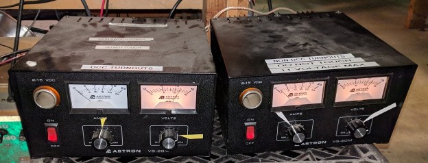
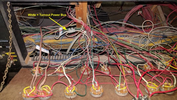
Slow-motion turnouts are powered by two regulated DC power supplies, one for DCC turnouts and one for non-DCC turnouts (there’s a 3rd AC power supply for twin-coil turnouts as used in the yards). Checking them showed that the non-DCC turnout power supply had shut down. This happens typically when there’s a short on the power bus and the power supply protects itself.
The power supply has a 10A fuse in series on its output, so a quick test is to simply open the fuse, and indeed this allows the power supply to start again. Once the circuit was open, with an ohmmeter I checked the turnout power bus and it clearly showed a short.
Description of Fix
The non-DCC turnout power bus is connected to at least the following panels:
- The Valley Turnout Panel
- The Mountain Turnout Panel
- The Passenger Turnout Panel
- The Bridgeport Turnout Panel
- The Lodi Turnout Panel
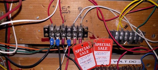
To narrow down where the short originated, I disconnected the turnout power bus on the Valley Panel (white wire) at the domino terminal connector. I started there since it was the last turnout panel I had used:
This did not isolate the fault.
I followed with the Mountain Panel (white wire at the terminal block):
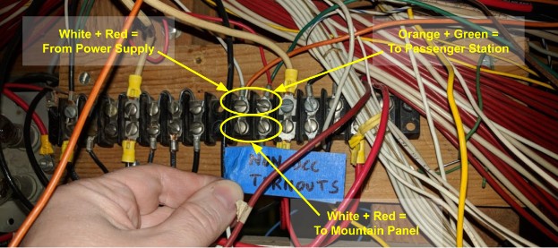
Unplugging the white wire from the terminal block (bottom part) did the trick and restored the power to all the other turnouts.
Once the short was isolated, I simply used the ohmmeter and tried all the turnout toggles from the panel connected to the non-DCC power supply. This showed that the culprit was the T320 toggle which I was having a problem with two days ago: when set in Normal position, it would create an intermittent short on its input pins if the toggle was pushed in a certain way.
Temporary Fix
As with other repairs, the first task is to restore the most important functionality. The actual repair will come later.
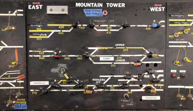
Since we do not currently need to manually toggle any turnouts on this panel, it is OK to leave the unplugged. There are actually two kind of toggles on this panel:
- 10 of them with black number labels are actually controlled by DCC. They can be thrown using the ACCY key on the NCE ProcCab controllers. They are powered by the “DCC Turnouts” power supply.
- The rest are the legacy toggles. They are manually thrown from this panel and are powered by the “non-DCC Turnouts” power supply.
It’s the latter that has been temporarily unplugged for this panel.
Fix time: 2 hours.
Follow-up Fix
The follow-up is to remove the temporary fix and fix the turnout toggle properly.
The short should be easily fixed by replacing the 6PDT rotary switch.
However I think it would be more appropriate to finish the DCC conversion of the full panel. This would also at the same time allow to rewire the panel and simplify it considerably, as it’s a bit messy:

There are actually multiple things going on on this panel:
- The original mainline turnouts are “logically” wired with their red input taken from a terminal block. The white wire is done using a bare copper metal wire, exposing the ground to pretty much everything.
- On the output side, colored white and green, for some reason all the green wires are also connected to a terminal block, yet inexplicably all the white wires are connected directly without an intermediary terminal block.
- On top of that, some of the red wires are from the DC track power bus, as one of the interchange tracks has a polarity selector on this panel.
- Finally there’s a completely unrelated bare copper metal wire and smaller wires. These are connected to nothing, and seem to correspond to an earlier scheme where the turnouts where selected using push buttons instead of rotary contacts.
Instead I would opt to simply convert all the turnouts to DCC:
- There are 20 turnout toggles on this panel so it needs 3 Switch-8 total.
- Add two more Switch-8.
- Some of these are Fulgurex and not Tortoise turnout motors. They cannot be connected to the Switch-8 directly, they need an extra intermediary relay board. 6 are needed. The main track map lists exactly which ones.
- Wire the turnout green/white wires directly to the Switch-8, with a row of relay boards where needed. That will eliminate many intermediary wiring to and from a secondary set of terminal blocks.
- All power bus can be removed from turnout toggles.
- Optionally, wire the turnout toggles to NCE Button Boards to still have some remnants of manual control. 3 of them are needed and they need to be reprogrammed using my special firmware since the NCE Button Boards are not compatible with permanent contact toggles as used on these panels. However since this panel is seldom used, I really wonder if that’s actually useful. It’s easier to switch the turnouts using the NCE ProCab.