The Randall Museum in San Francisco hosts a large HO-scale model railroad. Created by the Golden Gate Model Railroad Club starting in 1961, the layout was donated to the Museum in 2015. Since then I have started automatizing trains running on the layout. I am also the model railroad maintainer. This blog describes various updates on the Randall Museum Model Railroad and I maintain a separate tech blog for all my electronics & software not directly related to Randall.
2020-03-06 - DS64 for Turnouts Control
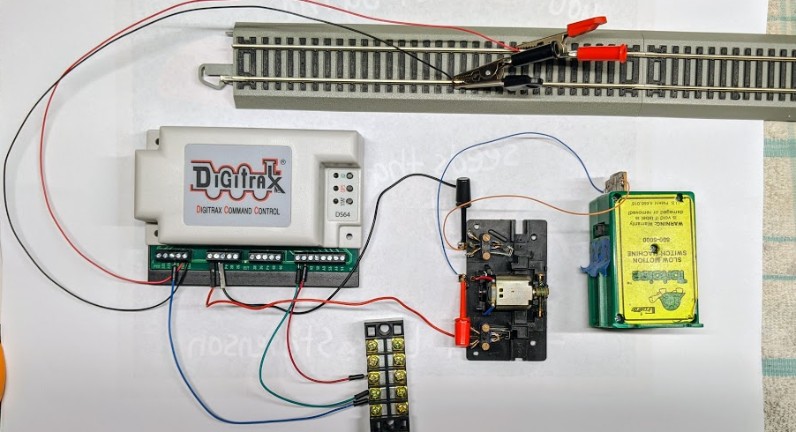
Category RandallConnecting a Digitrax DS64 to control both a Tortoise and a Fulgurex via DCC:
According to Digitrax tech note KB273, this configuration cannot be used as the Fulgurex takes “about 400 mA” when running, which exceeds the specifications of the Digitrax DS64 as well as ones of the NCE Switch-8.
Fulgurex and NCE Switch-8: Does not work together. I do confirm that the NCE Switch-8 cannot drive a Fulgurex directly (although it works when using the NCE Relay Board to do so).
Fulgurex and Digitrax DS64: Results are mixed. In a standalone test, I had no problem driving a Fulgurex directly with a Digitrax DS64. In situ at the museum I had one success case and one failure case. What happens is that the Fulgurex does take a lot of power, around 200 mA with a lot of variation. This exceeds the specs of the DS64. Looking at voltage, I noticed it was not symmetrical: Full 12 V voltage driving the Fulgurex in one direction but voltage dropping to 3~5~8 V when driving it in the other direction. This means we’re exceeding the current capability of the DS64 output and thus voltage drop. If some Fulgurex has a low enough impedance, it may work. If it has a higher impedance, it does not.
Let’s see how to use this. Instructions follow, let’s start with the documentation:
https://www.digitrax.com/media/apps/products/stationary-decoders/ds64/documents/DS64_flattened.pdf
Power:
- I do not want it powered from the track (as shorts would make it inoperable).
- PS14 plug or AX1(-)/AX2 (+) with 12-14 V DC supply.
- Our DCC power supply is set to 11-12 V DC and may be good for that.
- Can we have AX power and TRK A/B connected at the same time? Apparently no.
I do have an issue here with power. I don’t see a toggle to disable power from TRK. The doc seems clear that power from the track would generate a DC output at “the same level”. I’m going to guess around 16 V? That seems a bit high to drive a Tortoise or a Fulgurex.
One thing that is nice on the NCE Switch-8 is that it can be powered via the barrel plug yet be connected to the DCC for command control. There's a physical power selection switch. The DS64 lacks that, and careful examination of the board shows that all the various power inputs are “merged” together. Thus it does not seem safe to use more than one power source.
Trying it at home, one my NCE Twin command station:
- Track voltage is shown as “14 V AC” on a multimeter, knowing that the RMS computation is of course wrong, but that’s enough to get a rough idea.
- Once connected to the DS64 via TRK input, measuring the outputs in slow-motion motor mode shows a voltage of around 12 V DC.
- Connecting a Fulgurex to it, the voltage outage drops to 7~8 V DC while driving the motor.
- Update: Tested at Randall, when powering two Fulgurex in cross-over configuration, the voltage drops to ~4 V DC, yet it still manages to power them and gets the job done.
- The DS64 has no problem driving both a Fulgurex and a Tortoise on the same output (which is the cross-over situation I have on turnouts T150/151 that I need to control turns out that T151 has two Fulgurex and T150 has two Tortoises). See above why results may vary from one Fulgurex to another.
My main reason to not power it from the DCC: if a train derails on a turnout, it shuts off the power district. There’s no more DCC power, and thus the turnout machine cannot be powered to resolve the short. Sort of a catch-22.
Solution: Power it from another power district. That’s what I am doing for now -- the turnouts are on the Valley 2 district thus I power the DS64 from the Valley 1 district.
Apparently it’s common for LocoNet layouts to have a dedicated booster to power all the DS64 (or at least that’s recommended by the manual). If I ever have more than one DS64, I could indeed give them their own power district with their own circuit breaker.
The DS64 can power twin-coils or slow-motion machines. Need to set it up for the latter. There are other “OpSw” settings that can be set, each using a different AUX address. It does not need a PR3 to be programmer, it is done via DCC directly:
- Connect DCC to track A/B. No turnouts connected.
- OPS button held down for 3 seconds till blinks red/green.
- DCC remote send
AUX address 01 = Closed/Normal to set it slow-motion motors.
AUX address 09 = Closed/Normal to turn off output after 16 seconds.
AUX address 12 = Closed/Normal to use inputs A/S as absolute (S=closed state, A=thrown state).
- OPS button again till stops blinking.
Connect turnouts:
- To outputs 1-4 R/G in pairs. Invert polarity as needed.
Set DCC addresses:
- Connect to DCC.
- ID button held down for 3 seconds till blinks green.
- DCC remote send Normal/Thrown to 4 AUX addresses in a row.
- Confirmation via LED blinking for each.
- If got it wrong, restart for the 4 addresses.
Inputs:
- 8x A/S that seem like they can be used for the non-momentary rotary switch properly (S=closed/normal state, A=thrown state).
Testing the A/S input pins in “absolute” mode works as expected:
- When the A/S input changes, the DS64 output is powered to reflect the change.
- However the DS64 also reacts to DCC AUX commands to set the turnout.
- At power-up, the output is changed to match the wired A/S input as needed.
This is exactly what I want: when the layout is powered, turnouts should reflect the position of the physical toggles. After, they should reflect the last command “received”, whether it is via a DCC throttle or a panel toggle change.
For each output, there are 2 positions, R and G:
- DCC turnout set to “normal” or A input high: G < R (e.g. G=0 V, R=+12 V)
- DCC turnout set to “thrown” or S input high: G > R (e.g. G=12 V, R=0 V).
The observed A/S behavior is the reverse from the documentation.
To sum up the wiring needed:
- The DS64 would be placed behind the Valley Panel.
- DCC to TRK A / B.
- ⇒ Must use a DCC bus from another circuit breaker, not the one under control (or actually take it before the circuit breaker). Turnouts should never be powered by the DCC bus they can potentially short… (the documentation indicates that a typical strategy on a LocoNet layout is to have a dedicated power booster for all the DS64).
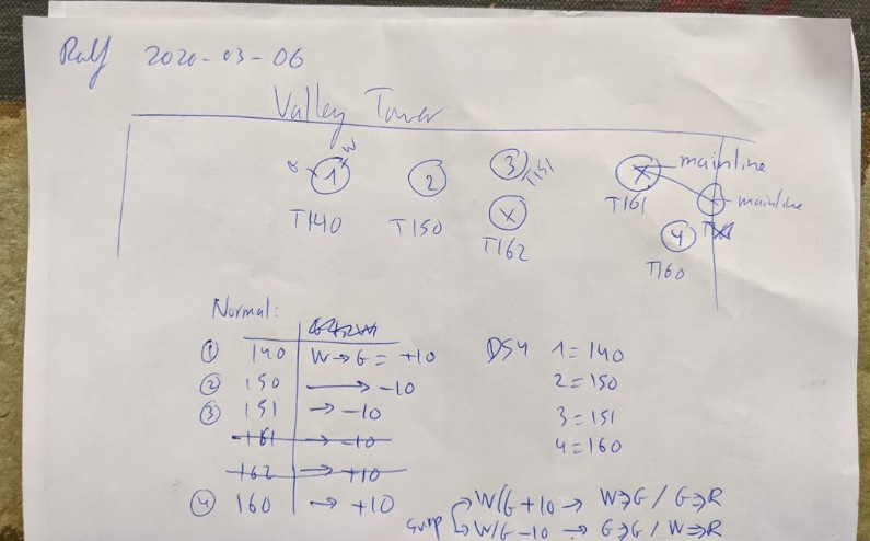
- Turnout 1 = T140 (aka Sultan)
- Turnout 2 = T150
- Turnout 3 = T151
- Turnout 4 = T160 (to Richmond Yard)
- For each turnout:
- Each panel toggle is a 6P2T rotary switch, with 2 white/green wires driving the remote turnout motor.
- Step 1: set the toggles to normal position, and note the polarity of the white/green wires. Observation shows that white = ground and green = +10 V.
- Step 2: Desolder the white/green wires from the 6P2T, and connect them to the R/G output from the DS64. Assuming the default white = ground and green = +10 V, green would go to the G terminal and white to the R terminal.
- Step 3: [Optional] Use one of the pole pairs and connect the DS64 common to the 6P2T input. Connect the 2 positions outputs to the DS64 using A=Normal and S=Reverse side.
I can only control four turnouts with one DS64. I selected those I remember seeing being used the most, namely Sultan, the T150 / T151 cross-over to mainline, and the T160 (to select between Richmond and Napa yards). That covers all cases. We don’t currently use the siding at Sultan as there’s an intermittent dead spot in the track in the tunnel (grrr), yet I plan to fix that, so I want the turnout working and controlled.
Final wiring notes: