The Randall Museum in San Francisco hosts a large HO-scale model railroad. Created by the Golden Gate Model Railroad Club starting in 1961, the layout was donated to the Museum in 2015. Since then I have started automatizing trains running on the layout. I am also the model railroad maintainer. This blog describes various updates on the Randall Museum Model Railroad and I maintain a separate tech blog for all my electronics & software not directly related to Randall.
2020-08-16 - Crossing Signal and Arduino
Category RandallJim is getting a new crossing signal for the Fairfield station:
This is to replace the previous version I did:
A bit of history on what happened to the signal that can be seen in the video, and a personal rant:
The old signal and its controller were removed by Marvin Chow when the GGRMC closed in 2015 -- from what I understand, he had donated such a signal a decade or so ago before leaving the club; the signal had failed and I had replaced it, and then he removed the one I had installed without asking anyone, claiming it was his and proceeded to donate it again to the Carquinez MRR. Rather pathetic to even claim to donate something and then take it back with the typical sleazy excuse of “well I didn’t really donate it, it was a loan”... sure. Whatever.
Anyhow, Jim got a new crossing signal, and we need to power it. Last time I connected it to a LogicRail Tech Grade Crossing Pro and its associated Bell sound module. These are the elements that were taken out unceremoniously. I could reuse the same -- they work well, within their limitations, or I could try to make an Arduino version and experiment in the process.
We are not getting a controller, at least not the Walthers controller for it: Crossing Signal Controller (949-4359). I checked the PDF and this is a typical 4-photoresistor setup, however it also needs a connection to the DC track to know the direction of the train. It expressly indicates it will not work with DCC.
In my plan to redo Fairfield and its automation, I was planning to also automate the crossing signal. However it makes more sense to build that automation separately. That will result in a more timely process, and it’s easier to simplify problems and deal with them separately.
I have these choices in mind:
- Arduino with photo-resistor setup.
- Arduino with Ultrasonic Ranging module HC-SR04.
- Arduino + ESP32-CAM using OpenCV for camera detection of trains.
- Arduino + ESP32-CAM and infrared LEDs.
Let’s explore this. Please keep in mind that I use “Arduino” loosely. By Arduino, I mean any small logic board, either an actual Arduino, or an ESP32, or ESP8266, or anything similar.
1- Arduino with photo-resistor setup.
The “trivial” choice is to replicate the typical photo-resistor setup. Crossing modules for model trains typically use 4 sensors -- 2 on each side of the crossing: A / B / <crossing> / C / D. The benefit of this is that the 2 sensors on one side are used to determine the direction of a train. For example sensors must be triggered in the direction of A then B, or D then C… that detects a train is arriving as well as establishes its direction, and signals the start of the flashing sequence. Similarly, the sensors being triggered in the proper direction in the other side trigger the end of the sequence.
The down side of photo-resistors is that they need to be calibrated for the room illumination, which can vary greatly. For generic control modules, we need to take into account that operators can obscure the sensors or create shadows, or that in a given room lights can be individually turned on or off. At Randall, for the Fairfield crossing we generally don’t have to care about operators casting shadows, however we are at the mercy of the operators or museum staff not turning on all the lights all the time. That’s a frequent occurrence.
This is typically solved by adding a 5th photo-sensor that is not located between the track, used to measure global illumination of the room. I don’t know many commercial modules which use that, however it is a common setup for DIY arduino-based setups.
The system needs to account that a photo-resistor may be covered by either one single engine for a very short period of time, or a long train, and space in the cars will create a “pulsing” effect. Thus a fairly high scan rate or some kind of window filter is required here, which any Arduino can trivially achieve -- as long as one keep in mind the idiosyncrasies of different Arduinos or ESP32 ADCs -- see that video from Andreas Spiess on the subject of ADC measurements.
A nice side-effect of having 2 sensors on each side is that we can approximate the speed of the incoming train, and potentially use that to delay when to start the crossing signal (modern real crossings try to start their warning at a constant time before the train arrives).
2- Arduino with Ultrasonic Ranging module HC-SR04.
This one is more about “brainstorming” than reality. Could the photo-resistors be omitted and an HC-SR04 module be used instead? For those not familiar, this is a very typical ultrasonic sensor that comes in many Arduino kits. It’s fairly easy to use -- start a pulse, measure how long it takes for the pulse to bounce back.
The immediate downside I’d see here is that these modules are fairly bulky -- at least from an HO-model size point of view. A typical sensor is about 1.5~2 inches wide. The other downside is that, from personally playing with some, I find them finicky and not very precise.
In the case of the Fairfield crossing, I could imagine us having two of these sensors, each looking at opposite sides of the crossing towards oncoming trains. Mounting them maybe ½ or one foot on some support pillars looking at the incoming track. On the track leading from Sultan towards Fairfield, we have the advantage that the scenery + the window barrier creates a “natural” canyon where the incoming train is the only thing that would move. On the side by the Fairfield station, we have the disadvantage that the scenery is an open town and there’s a lot less “tunneling” thus a lot more likelihood to measure some unrelated train.
The obvious question is whether the small cross section of an HO train would be enough to be detected by the sensor. I’ve played with these before and from memory they were both not precise, nor very sensitive. In particular, one issue was distance is measured by measuring the return pulse width, and that was a fairly noisy process.
3. Arduino + ESP32-CAM using OpenCV for camera detection of trains.
A while ago I was toying with the idea of using a Kinect for train detection. Although prices for this particular device have fallen drastically, most applications require a full computer to process the signal and do something with it via their SDK. In between, there’s been a wide interest into the usage of LIDAR and structured light sensors for depth sensing. Since this started exploding 5-10 years ago, luckily what needed a “full computer” back then can be reduced to a mere Raspberry Pi 4 or similar hardware today. Still the main issues with the tech remain, such as calibration, lighting consistency, and a limited depth range. Even though these solutions make for impressive demos, I am not sure about their long term reliability -- what I want is a solution that requires little to no maintenance, and can run for 300 days/year without calibration.
Years ago I experimented with using “dumb” video-based detection by detecting trains masking IR-reflective tape. No machine learning needed, no complex LIDAR nor structured light sensor. Processing was no different than using photo-resistors, essentially, however I had the benefit of being able to use cheap ipcams locked in infrared mode -- meaning the system was able to adapt to room illumination fairly easily.
In between I’ve been playing with the ESP32-CAM, which is a sub-$10 module combining a dual-core processor, and a camera. The camera can do 1600x1200, but more importantly we can do the processing right there in the ESP32 module. Using OpenCV, we can do the same kind of very basic pixel-based motion detection I had in my recent train-motion video project. No machine learning is needed here. All we need to do is detect motion against a known path.
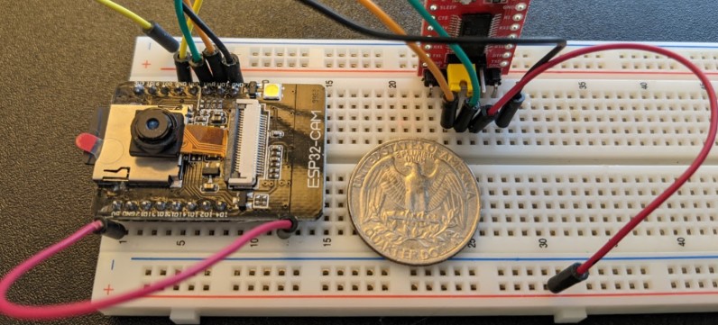
Here’s the ESP32-CAM which I’ve been working with recently and which I’d be using:
Left: ESP32-CAM with sdcard and OV2640 camera. 4 MB SPI RAM, 2 cores @ 240 MHz. Wifi + BT.
Right: Red board is an USB FTDI adapter. Quarter for size comparison.
This would work using one or two components. One is the ESP32-CAM, with the camera attached to it. These typically come with a camera attached to a ribbon cable of either ½ inch or 2-3 inches thus the camera cannot be too far from the ESP32. It would have to be mounted high enough to cover the desired area of track on both sides of the sensor.
To reduce false positives, an initial setup phase would have the operator setup the path of the track on a captured still. This does not need to be too precise, the goal is to be able to separate motion from parallel tracks. In an advanced version we could imagine a setup phase where OpenCV is used to find tracks in the image and let the user select the desired tracks -- yet for an initial version, just drawing a few straight line segments would be good enough. Most notably the setup must identify both sides of the crossing.
Once that setup is done, we can run basic motion detection to determine where motion happens on that path, and in which direction. From there we can apply the standard crossing signal algorithms.
One nice thing here is that we don’t need the full camera resolution. Downgrading the image to 800x600 or even 400x300 will result in faster processing for the pixel-based motion detection, yet provide enough detail to detect a single engine or a large train on the track.. We are interested in fast detection rather than visual detail.
The second component would drive the actual crossing lights. Depending on where the ESP32-CAM needs to be mounted to get a good view, it may not be possible to drive the crossing signal lights from the same ESP32. If possible, it would be great to use a single device, yet we need to account for the fact that may not be an option. In this case a secondary Arduino such as a Nano or another ESP could be used to drive the lights. Communication between both could be achieved using a simple wired connection (raising a signal on a pin, or 2-wire serial port), or via wifi or any other wireless option shared between both modules (such as ESP-NOW).
One of my goals is to use a similar setup to create software-defined block detection at the whole layout level.
Cost wise: An ESP32-CAM is around $10-15, and for the other side an ESP32-S2 is around $8 or cheaper.
This is my preferred approach for now.
4- Arduino + ESP32-CAM and infrared LEDs.
This is basically the same setup as the Camera + OpenCV version above, except we use the reverse of photo-resistors: infrared LEDs are embedded in the track, 2 on each side of the crossing. Thus instead of measuring ambient light, we use the camera to detect illumination from the track-mounted IR LEDs. When the IR beam is cut, it simply means a train is obscuring the sensor.
This can be beneficial if we want to narrow the detection area on the image feed. After an initial automated setup phase, the ESP32 could analyze just the location of the IR sensor on the image instead of doing generic motion detection on the whole image.
With this system, we can trivially automate the setup: when the module starts, it can detect each LED one by one, automatically finding their location in the image -- assuming the ESP32 is controlling these LEDs (directly or indirectly), it can turn them on one by one to identify them. The only fairly reasonable assumption is that the sensors are not covered by a train during that phase (which we can detect since we expect to find 4 IRs LEDs).
Ironically that is a tad more work to install than the pure camera-based motion detection version as it requires a bit more hardware (namely four extra IR LEDs and their wiring). However the possibility to automate the setup phase makes this particularly attractive and a good step up from the pixel-based motion detection.
5- If all fails…
The nice thing about this R&D is that “failure is an option”. I know I can deliver something using any of the options above. Eventually it’s not just about delivering “something”, it’s about delivering a solid and reliable experience that will not need ongoing maintenance once finalized.
If all fails, I will revert to the old and trusted LogicRail Tech Grade Crossing Pro and its associated Bell sound module. I’ve used these before, I can purchase them again and set them up just as I did before. Cost is around $100 for these.