The Randall Museum in San Francisco hosts a large HO-scale model railroad. Created by the Golden Gate Model Railroad Club starting in 1961, the layout was donated to the Museum in 2015. Since then I have started automatizing trains running on the layout. I am also the model railroad maintainer. This blog describes various updates on the Randall Museum Model Railroad and I maintain a separate tech blog for all my electronics & software not directly related to Randall.
2021-11-28 - “Cracker Jack” Illuminated Billboard
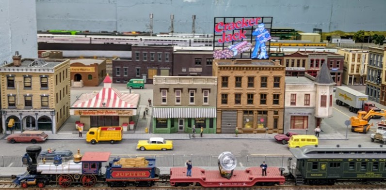
Category RandallToday Allen and I finally got the “Cracker Jack” illuminated HO-sized billboard powered by the layout’s building lighting panel:
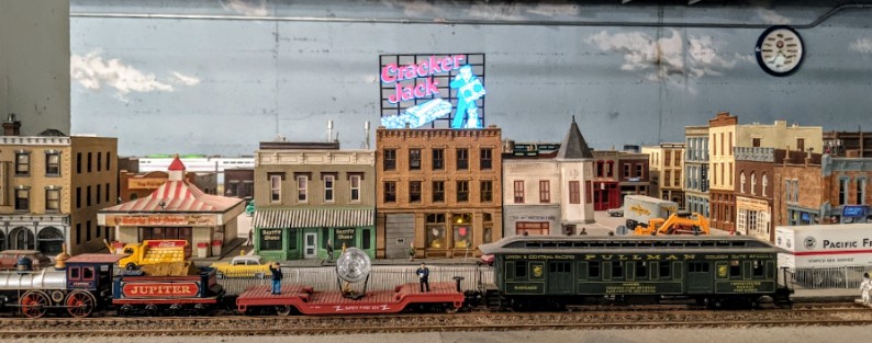
Even with the full room lights on, it’s still quite visible and should be a nice animation for visitors:
Back in June, Allen got the billboard and we temporarily installed it, yet it remained unpowered. The sign can be powered via a battery and instead I wanted it connected to the layout’s building lighting circuits using an Adjustable Voltage Regulator.
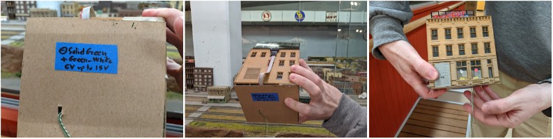
That project took a bit longer than expected -- first I plugged the voltage regulator in reverse (thus increasing the voltage instead of reducing it), and that killed the billboard’s control board. So I got a replacement for that, and this time wired it up correctly. Allen and I made the building self-contained with the voltage regulator and I tried adding an orange LED inside to add some scene lighting, which honestly didn’t work and is quite sub-par.
The voltage regulator should help -- the layout’s building power supply delivers 8~15 V -- 15 V without load, and drops to 8 V with the old incandescent bulbs on, which is quite the drop. That means turn circuits on or off could damage a board that requires a specific voltage like this one. What where the voltage regulator comes in -- it accepts 3-40 V in input and will deliver a constant output no matter what the building power supplies delivers.
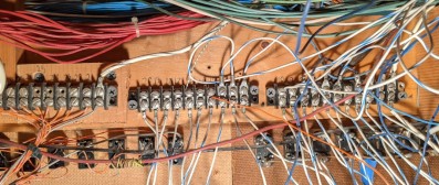
Then things got even more delayed when I fell in the rabbit hole of trying to understand the building lighting panel. Finally I got that figured out and documented in my layout documentation recently. At least that was quite useful because it made the final connection seem trivial since all the prep work had been done before. That’s what the wiring looks like:

So now it’s all in place and powered and working.
One thing we could use is some better labeling of the building lighting panel. All the unlabelled toggles in the middle are connected, yet I am still not sure what they exactly power, if anything. I could use some help there.
The base of the building is loose and no longer glued because I wanted to be able to access the inside easily. One trick I learned recently is to use magnets -- glue some light magnets on the base plate and the building and that will hold both pieces together. That’s an easy addition that someone could help with.
Finally the other thing I'd do differently is 3d-print a diffuser for that orange LED inside. The light is too focused to be visible from the outside. That’s an issue I found with all modern LEDs -- they appear very bright because the light is focused and coming only from the top, so they look bright when looked from the top yet almost no light is emitted on the sides. That is of course ideal for LEDs on panels, but not so much here. One trick I’ve been using is to roughen the plastic with a bit of sandpaper, and also to apply a dab of white glue on the LED. That reduces the intensity from the top and diffuses it a tiny bit, but that’s clearly not enough for this house interior.