The Randall Museum in San Francisco hosts a large HO-scale model railroad. Created by the Golden Gate Model Railroad Club starting in 1961, the layout was donated to the Museum in 2015. Since then I have started automatizing trains running on the layout. I am also the model railroad maintainer. This blog describes various updates on the Randall Museum Model Railroad and I maintain a separate tech blog for all my electronics & software not directly related to Randall.
2022-09-18 - Work on T1 and T2 Turnouts
Category RandallAllen and I started looking at what it would take to fix the mainline crossover T1-T2 in front of Stockton Station.
From my notes back from 2017, one side has a broken switch rail, and the other side has no power on the frog, and something in there was shorting when thrown.
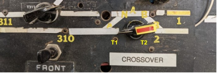
First, which is T1, and which one is T2? Turnouts on the Stockton Yard side go form T6 down to T3. Thus it makes sense the next one is T2 from the yard, followed by T1, away from the yard. I will need to label them on the layout fascia to remember that. I have an older track plan with the turnouts labels inverted, and then a newer one with them correct:

The toggle on the panel did not operate, and after a while I remember I had powered off the entire turnout panel because something was shorting all turnouts in there. And we don’t really use the panel, so fine, it’s basically unpowered. Looking behind, it’s quite a jungle in there:
Each time I open this panel, I want to tear apart all this mess and clean it up.
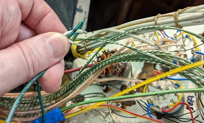
In that picture I’m holding the 2 wires for both T1 and T2. 2 green wires and 2 white ones. Each turnout has one green and one white, but which ones pair together? No clue. I took an educated guess at which 2 wires are likely to pair together and marked these with black marker, and of course I don’t know if that’s for T1 or T2.
I thus spend the next 15 minutes crawling under the layout trying to follow one of these wires. It was a bit of a painful chase as the wire went through a convoluted non-direct route starting in the opposite direction of the turnout!
After a while I traced this to T2. Here’s what we have under the turnout:
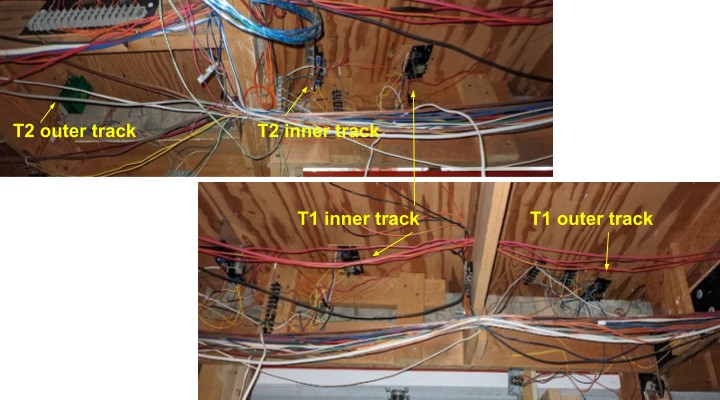
The important data I needed to see here is that:
- T2 has one Tortoise (outer track) and one Fulgurex (inner track).
- T1 has 2 Fulgurex.
T2 is the one with the broken switch rail, which I don’t know how to fix, so we’ll put it aside.
T1 is the one I care most about. If I could get it to work, it would allow us to get out of the yard using the inner track and easily move to the outer track. Powering up the turnouts using the 2 green+white wires from the turnout panel did not do anything, so now I need to poke them in-situ with a 12 V power supply to verify whether the turnout motors actually work.