The Randall Museum in San Francisco hosts a large HO-scale model railroad. Created by the Golden Gate Model Railroad Club starting in 1961, the layout was donated to the Museum in 2015. Since then I have started automatizing trains running on the layout. I am also the model railroad maintainer. This blog describes various updates on the Randall Museum Model Railroad and I maintain a separate tech blog for all my electronics & software not directly related to Randall.
2025-06-04 - Research: SIA+DFS Turnout / Block Control
Category RandallOne thing both Orion and I would like is better usage of the SIA + DFS.
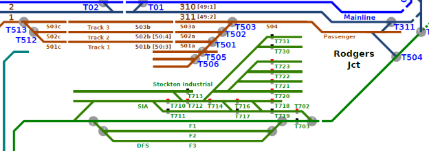
The SIA + DFS offers 6 tracks:
- The left most track for the Trolley… I’d like to reserve that one once I automate it again.
- 2 “mainline” tracks for the SIA.
- 3 “sidings” tracks for the DFS on the right.
These are the tracks in green on the schema / plan v8: Randall Map - Track Plan + Sensors 8.pdf
There are 2 separate issues here:
- Control of the turnouts.
- Power routing for the tracks.
Turnout control is hard because it’s split between:
- The SIA panel
- The DFS “seize-release” on the Stockton / Mountain Panels.
That makes it incredibly annoying to use.
- The SIA has old-style twin-coils. I would not try to provide DCC control for these.
- The DFS has 5 Tortoises. These are the ones I’d connect to a Switch-8.
- The Switch-8 is incompatible with our panel rotary turnout toggles, and that’s not an issue here since these are not on any given panel. On the contrary, their control is on two panels using a complex seize-release setup. Thus a Switch-8 control with no panel access would be easier to use. We just need a schematic with a reminder of the AUX turnout numbers and we can operate them via JMRI (Orion’s TCS, or Engine Driver) or via NCE cab.
The only thing is that I need to understand how the seize-release control stuff works.
I believe that power routing is setup as follows:
- For the SIA, block toggles on the SIA panel → not a problem.
- For the DFS, the siding power is tied to the track alignment via the DFS electronics and the seize-release buttons.
The Track Power Routing for DFS document explains the background behind the choices. They made sense from a DC perspective. For DCC, we don’t really need that complexity anymore.
This schema “explains” it all… sort of: DFS - Track Power Routing [2018].pdf
What I would suggest instead is:
- The SIA already has its dedicated DCC circuit breaker.
- Power to the DFS should come from the same location.
- SIA LOCAL means the SIA is powered by the Booster 4 P4 SIA.
- SIA AUTO means the SIA is powered by the DFS electronics.
- The Auto/Local toggle should be disabled. According to the explanation above, what we want is to be fixed in the “Local” mode.
- The DFS siding power is the problem.
- It is my understanding that the siding power is governed by the AUX relays on the Tortoise, and they take their power from whatever lead track is connected on the East/West side of the yard. That’s fine in DC because the DFS electronics only opens a Tortoise on the East or West side of a turnout, but never both at the same time (at least I think… need to double check that). But if we have independent Tortoise control, that means a track can be powered from both ends. That would be acceptable only if the East/West approaches are on the same DCC circuit breaker / booster circuit.
- That “understanding” is wrong. Actually the siding power is provided by the DFS controller.
- We would not use the DFS electronics power for the sidings and instead would power them directly from the Booster 4 P4 SIA, the same that powers the “SIA LOCAL” input.
- Before we do that, we need to ensure there is electrical isolation on each side of the yard and their corresponding approaches. It should already be the case (otherwise the current setup could not work to begin with) but we need to double check that.
- We need to decide whether the DFS F1 / F2 / F3 are always powered or we want to have toggles switches to turn them off.
- Polarity is fine on the East side (Stockton). It can be an issue on the West side when aligned towards the Branchline. That’s why we need electrical isolation. We also need that second part of the Branchline to have a polarity inverser.
In summary, the work to do is:
- Validate whether the current DFS allows opening both Tortoises at the East or West of a given DFS track at the same time.
- Validate we have track isolation on the East / West approaches.
- Disconnect the SIA AUTO / LOCAL.
- To start, we’d just validate that everything works with it in LOCAL mode.
- Validate that LOCAL is connected to Booster 4 P4 SIA.
- Disconnect power routing to DFS F1, F2, and F3 from the DFS electronics panel.
- Instead tie them directly to the same input as the SIA LOCAL.
- Long term we’d want a dedicated terminal block for feeders.
- For a quick test, we can use the O/P SIA after disconnecting it as it leads to the SIA AUTO/LOCAL. At least in theory it does, but we should never assume the schematics are (still) accurate.
- We need to disconnect the 5 Tortoise from the DFS electronics panel and connect them to a separate Switch-8, which would then be powered by the DCC Turnout bus (and not the Booster 4 P4 since it’s a circuit breaker).
- Ideally all these changes would be done as local as possible on the SIA panel itself.