The Randall Museum in San Francisco hosts a large HO-scale model railroad. Created by the Golden Gate Model Railroad Club starting in 1961, the layout was donated to the Museum in 2015. Since then I have started automatizing trains running on the layout. I am also the model railroad maintainer. This blog describes various updates on the Randall Museum Model Railroad and I maintain a separate tech blog for all my electronics & software not directly related to Randall.
2025-12-29 - Work on the DFS Yard and an Explanation
Category RandallI’m tackling the “DCC conversion” of the DFS Yard. This 3-track yard adjacent to the SIA is controlled by a fairly complex electronic board, designed by Mr. Perry back in 2009, that controls its track power in a fairly fancy way adequate for the old DC layout, but now-a-day entirely obsolete.
|
|
|
|
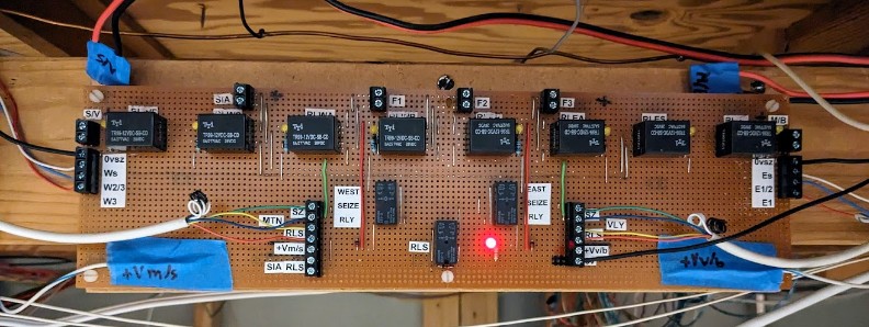
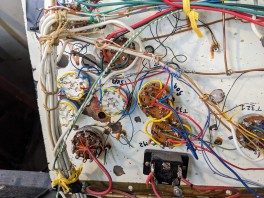
And because it was designed by Mr. Perry, the awesome thing is that I have schematics for every part of the components, which is a good thing because that power routing looks totally intimidating at first:

DC Usage
This electronics makes entire sense on a DC layout. The power routing works as such:
- The yard can be powered by 3 different sources -- the SIA Panel, the Stockton Panel, or the Mountain Panel -- but never more than one source can power the yard at the same time.
- When a train must enter the yard from the Stockton Panel side, the users press a “Seize” button on the Stockton Panel. This ensures that the DFS tracks are powered by the DC power from the Stockton Panel -- and it disconnects power from the Mountain Panel.
- When a train must enter the yard from the Mountain Panel side, the users press a “Seize” button on the Mountain Panel. This ensures that the DFS tracks are powered by the DC power from the Mountain Panel -- and it disconnects power from the StocktonPanel.
- Each panel also has a “Release” button to stop powering the yard from either side.
- When a train needs to operate only within limits of the yard, the “Auto/Local” toggle on the SIA panel can be placed on the “Local” side. This powers the tracks from the SIA panel.
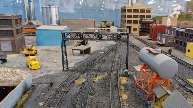
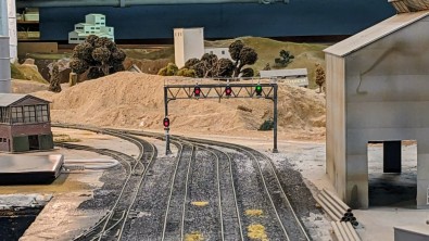
- The signal bridges over the entrance on both sides are tied to the power routing and will only show a green indication when their side powers the track. This is a perfect visual indicator: if one side has all reds on a signal bridge, a train should not cross that signal bridge as it does not have the power routed correctly for it.
Similarly, the turnouts to enter or exit the yard from the Stockton Panel side are controlled by the toggles on the Stockton Panel itself. And the turnouts to enter or exit the yard from the MountainPanel side are controlled by the toggles on the Mountain Panel itself.
DCC Usage
All that scheme above made sense when the yard was used in DC. But when we’re using DCC, it brings a lot of complexity that is not useful anymore:
- Depending on the position of the Seize/Release buttons, the yard may be powered by the DCC boosters attached to the Stockton yard power district, or the Mountain power district, or the SIA power district. That means the yard is affected by any short in these other places, and inversely can short the other locations.
- When we are in front of the DFS tracks, we’re next to the SIA panel, and that panel only. We do not have access to the Seize/Release buttons for the power routing as they are located on other distant panels. Similarly, we cannot change the turnouts because they are located on the Mountain or the Stockton panels which are far away from the DFS yard itself.
- The signal bridges on the yard entrance and exit should no longer be “all red” and should indicate which track is aligned.
What we really want for DCC operation is:
- Bypass all the complex Seize/Release power routing scheme, and power the DFS tracks solely from the SIA panel power.
- Have access to the turnouts from anywhere.
Note that these are two separate goals.
As usual, I decided to proceed with multiple phases. The first phase is mostly validation -- make sure I understand everything and that I am able to modify things adequately. Once that is done and that we have used the new way for a while, the next phase will be to clean up and remove obsolete wiring and equipment.
Rewiring the turnouts for DCC operation
That part was actually trivial: the turnouts are all modern Tortoise, with their control wires going directly to the Stockton Panel and the Mountain Panel respectively. The goal is to instead wire them to an NCE Switch-8, which will allow us to control the turnouts from the NCE PowerCab or from the JMRI computer and WiThrottle.
|
|
|
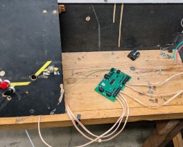
An NCE Switch-8 was placed next to the SIA panel as I found that the current turnout control wires, once desoldered from the Stockton and Mountain panel, were just about the right length to reach the SIA panel. Very convenient.
What’s Next:
- The NCE Switch-8 is temporarily powered by the DCC power from the SIA panel. This is not desirable long term -- if an engine shorts against a turnout in the yard, we’d lose yard power and thus we would not be able to throw the turnout. The proper way to do this is to power the Switch-8 from a different power supply.
- Instead I need to pull wires from the isolated DCC turnout power supply which is dedicated to that purpose.
Rewiring the Track Power Routing
I first checked that all the 3 DFS tracks were properly isolated from the turnouts, and indeed they are. Both rails are isolated, they don’t even share commons. That’s good to know!
Rewiring the 3 DFS tracks was trivial: I just used the existing power leads, but I disconnected them from the electronics “Switching Panel” (the board with all the relays) and wired them directly to the DCC. I also bypassed the “auto/local” toggle as it was now redundant. In essence, I wired all the DFS tracks to always be in “local” mode.

What’s Next:
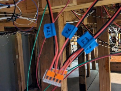
- We now lack a way to individually turn each DFS track on and off. This is a very useful feature in a yard as it’s desirable to turn power off when parking engines long term. Eventually what I’d like to have are 3 track on-off toggles on the SIA/DFS panel.
- I also need to change the dangling Wago connectors for a proper terminal under the panel.
Rewiring the Signal Bridges
In the DC usage mode, the signal bridges on both sides are wired in such a way that they become all-red when power is not “seized” on that entrance/exit. When that happens, the signal bridges no longer reflect the state of the turnouts.
In DC mode that makes sense as it clearly indicates that a train should not cross the signal bridge as the power on the other side of the track does not match. But in DCC we don’t care. We want the signal bridges to always show us how the turnouts are aligned.
The question is how does the “Switching Panel” electronics board do that?
Luckily, courtesy of Mr. Perry, we have the schematics for it right here (click on this for a better view):

Now that thing sure looks intimidating, yet it's not that bad. It's essentially a bunch of relays forming logic gates, and I implicitly “translate” and read this as a bunch of boolean logic equations.
I noticed that a few of these relays are configured to be self locking: once power is applied via an intermittent button push, the relay closes a circuit that powers the relay itself, and thus makes sure it stays closed.
Let's examine the schematics above:
- At the top level are the 8 relays that power the 3 DFS tracks.
- When the Stockton/Valley seize button is pressed, it closes a relay to enable power to be fed from the Stockton side, and then, depending on which track is selected, sends that power to the track. So that accounts for 4 of the relays at the top.
- And then there's a similar arrangement for the other side with power from the Mountain.
- At the same time, the relay from one side disconnects the power input from the other side.
- The “seize” from one side also grounds the output signal named “0vsz”. That signal goes to the signal bridge’s “Dow Yard signal controller” to allow it to display the turnout state in green.
Both the “Switching Panel” schematics as well as the “Dow Yard signal controller” schematics were puzzling at first until I realized that most of the logic is triggered by control lines that are grounded when active. They are tied to the positive of the power supply by default. This is simply what we call “active-low control lines!” Once I understood that, the schematics made much more sense. It now makes sense that the output “enabling” the signal controller is labelled “0vsz” as it is probably an abbreviation for “zero volts seize”.
Which means now I realized that I could bypass the entirety of the complex power routing switching panel by doing 2 simple things:
- Disconnect all the input power leads. The panel is not routing any power anymore and doesn’t need to be actually powered at all.
- Tie the “0vsz” lines to the ground of the power supply. That enables both signal bridges to show a green state based on the turnouts’ positions.
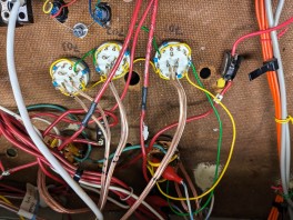
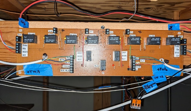
And that’s what I ended up with:
This makes it work as I need. I labeled every wire so that I can easily revert things if needed. The Switching Panel is entirely bypassed. Yet, from an initial test, it behaved as I wanted.
What’s Next:
- Instead of bridging both “0vsz” wires to the ground on the panel, I should do that directly on both remote Signal Controller boards. Then the black wires can be removed.
- Similarly the 3 wires to the West (Ws, W2/3, W3) and the East (Es, E2/3, E3) are no longer used and can be removed.
- The two red-black power routing input wires at the top can be removed.
- The Seize/Release button wires can be removed.
Conclusion
The first phase was a success so far. I have a usable DFS yard. The track is powered by the SIA panel. The turnouts can be controlled using the NCE PowerCab.
The next phase is to do cleanup, which I will do slowly as I go along:
- Remove a bunch of wiring that is now unused.
- Tidy up the SIA panel.
- Add toggles for each of the DFS tracks to turn them on/off individually.
- Use a proper terminal block to wire the DFS tracks instead of Wago connectors.
- Update a bunch of schematics to show the new DCC turnout numbers:
- the main layout map,
- the Stockton Yard panel map,
- the SIA panel map.
- All the information I wrote here should also be collected in the main layout description document.