Model Train-related Notes Blog -- these are personal notes and musings on the subject of model train control, automation, electronics, or whatever I find interesting. I also have more posts in a blog dedicated to the maintenance of the Randall Museum Model Railroad.
2017-04-12 - Powering a LED off DCC
Category DCC
Very interesting discussion here: http://cs.trains.com/mrr/f/744/t/230553.aspx
Summary, TL/DR: We can power a LED directly from DCC, just add a resistor to limit to about 10 mA (or less if too bright).
Suggestion is "nice to have" a reverse parallel diode to limit the reverse voltage on the LED:
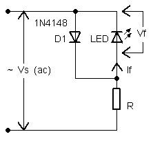
However another comment indicates it's enough to compute R to be within the specs of the reverse voltage of the LED (assuming I have the specs).
From [richg1998]: "The NCE Power Cab uses a red led and a 1k resistor to monitor the AC out of the Cab. … No reverse diode…"
That's a good point. SGTM.
This is nice and could apply to Randall on the reversing loops:
[Mark R.] "I have four signals on my DCC layout that give polarity indication going into reverse sections. The green LED is attached to opposite rails on either side of the gap, and the red LED is attached to the same rail on either side of the gap. These LEDs have been running straight off of DCC track power with no inverse protection for over 15 years and have not damaged any of them."
Let's think on how that works electrically by taking an example. Let’s say we’re looking at the “end” of a reversing loop that uses a manual toggle to reverse the polarity.
And if the rails polarity is A/B, we have across the gap:
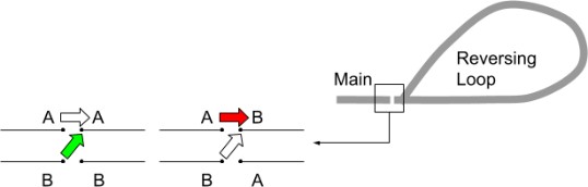
Since it's a sort-of-AC signal, the 2 LEDs can be on either side:
- The red can be on either rails, bridging the gap on the same side.
It will be off when the polarity matches (same voltage), on when mismatched. - The green can be across opposite sides of the gap.
It will be off when the polarity matches (which is improper), on when mismatched (what it should be). - It's interesting because we can do it with just 3 wires, one being common to both LEDs.
Now imagine the 2 LEDs are assembled to look like a dwarf signal placed next to the reversing loop turnout. It would make a visual indication on whether the power toggle is in the right direction. Even when using an automatic reverser module, this would be a nice display to have.
We can use the exact same principle to power a green/red mast to indicate alignment of a turnout, e.g. in the case of Sonora at Randall when we have 2 tracks going into one by using the polarity of the frog as a common to both LEDs.