Model Train-related Notes Blog -- these are personal notes and musings on the subject of model train control, automation, electronics, or whatever I find interesting. I also have more posts in a blog dedicated to the maintenance of the Randall Museum Model Railroad.
2018-09-02 - Digispark Tiny
Category Arduino
The Digispark Tiny is probably the most basic and compact Arduino-like I’ve worked with. It’s about the size of an USB A plug. It is powered by an ATTiny85 and offers 1-5 I/Os depending on usage (typically 2-3).
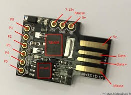
(image source: mister-bidouilles.fr)
Kickstarter Date: 2014.
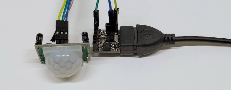
Example of the Digispark Tiny connected to an USB OTG with a PIR sensor:
The Digispark Tiny is made by Digistump. That was the first mini Arduino made by this manufacturer and the actual product name is just “Digispark”. Since there has been other versions after (Digispark Pro, Digispark Oak), I call the first one “Digispark Tiny” to differentiate it.
- Manufacturer: Digistump
- Wiki link: http://digistump.com/wiki/digispark
I don’t think it’s being sold or even manufactured anymore (there are some lingering on eBay or Amazon). It used to cost $10 a piece, which back in 2014 was a good price for this. For half that price Digistump now offers the next version, the Digispark Pro (it’s really $5 in packs of 10, or $10 for one), which has more I/Os, and drastically less limitations.
The DigiSpark Tiny (as well as the Pro) are not pure-Arduino compatible. I call them “Arduiino-like” instead. Digistump used to provide a custom version of the Arduino IDE with a specific toolchain for the Digispark. These days the regular Arduino IDE can be used and the custom tool chain added to it using the Board Manager. The other specific detail is that the serial port does not work like a regular Arduino serial port.
To use this Arduino, the older Arduino IDE 1.6.5 is needed (not the newer ones); there are instructions on the wiki to setup the AVR Board in the Board Manager: http://digistump.com/wiki/digispark/tutorials/connecting
Following are my usage notes, just my shorthand for info gathered from the forums & wiki so always refer to these when not sure about specs.
DigiSpark Tiny Pin Guide: http://digistump.com/wiki/digispark/tutorials/pinguide
Pins summary:
- P0 = AREF, I2C SDA, DI (or D1?), PWM.
- P1 = D0 , PWM, Led on Rev2.
- P2 = D/A, I2C SCK, ADC1.
- P3 = D/A USB+, ADC3, (1.5 kΩ pull up).
- P4 = PWM, D/A, USB-, ADC2.
- P5 = D/A, ADC0 -- says it's 3V at high instead of 5V, use for non-current application.
- VIN pin takes 7-12V and can output 500ma (but over 100-200ma or over 6V might need some heat sinking).
Notes:
- P0 is safe to use for digital I/O, 5V.
- P1 is connected to the LED.
- P2 is safe to use for digital I/O or Analog input (ADC1), 5V.
- P3 & P4 are used for software USB. Can’t use them and USB at the same time. They have 3.6 V zener diodes. P3 has a pull up.
- P5 is 3V max with “limited” current application.
The really nice thing about the Digispark is that I’d just plug it in a regular sized USB A connector, and this has a great advantage: I can plug it on any Android device using any USB OTG adapter, and read from it via the USB interface.
Contrary to traditional Arduinos, the Digispark Tiny does not provide a real serial port over USB. USB handling is done in software and basically uses a hack by exchanging characters using USB control messages. There’s a small C binary provided to read it from the host side, and I have reverse-worked how to use that on Android.
I wrote a post on the Digistump Forum explaining how to read the USB “serial port” from Android: https://digistump.com/board/index.php?topic=1675.0
Example 1: Reading a potentiometer
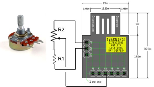
To use with a Tiny: variable resistor is powered between GND and 5V. The analog input P2 is used (aka ADC1). The Arduino API by default samples with a 10-bit value (1024). R2 would be something like 10 kΩ (5V / 10 kΩ ⇒ 0.5 mA). R1 can be omitted unless you want some kind of offset.
In the Arduino sketch, I made a micro serial protocol: Android device sends a “r” character to read the value, which comes back as a decimal number. Android device can also send a “b” character to make the on-board LED blink. Then an Android AsyncTask runs this in a loop, blinking the LED each time a value is read.
Arduino sketch:
#define USB_CFG_DEVICE_NAME 'D','i','g','i','T','h','r','o','t' |
See https://digistump.com/board/index.php?topic=1675.0 for an overview of how to use this on the Android side.
Example 2: Reading an HC SR501 PIR Sensor
PIR arduino sensors (1 pack of 5 for $10ish): https://amzn.to/2IB9P20
(image source: the internet)
To use with a Tiny:
- PIR VCC to Tiny 5V
- PIG OUT to Tiny P0 or P2, mapped as digital input.
- PIR GND to Tiny Gnd
Arduino sketch:
#define USB_CFG_DEVICE_NAME 'D','i','g','i','S','R','5','0','1' |
There’s a bit of a subtlety here: The SR501 is internally a 3V device so the OUT pin is 3V when on. Since the Digispark is a 5V device, the I/O pins reads a high when the input is 3V. So “normally” that works out fine. Unless for example you place a LED on the SR501 output, or anything else that may causes enough voltage drop to not register the high state on the IO pin. A workaround is to measure it in analog with a lower threshold. Here’s an example doing just that:
~~