Model Train-related Notes Blog -- these are personal notes and musings on the subject of model train control, automation, electronics, or whatever I find interesting. I also have more posts in a blog dedicated to the maintenance of the Randall Museum Model Railroad.
2025-11-19 - HO Live Camera Car v2: Power (part 3)
Category Video
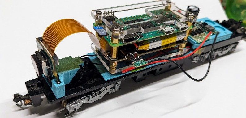
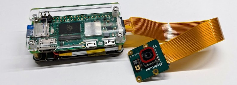
I’m building an HO-Size Camera Car. In the first post, we selected a Raspberry Pi Zero 2W for the processing unit and in the second post we selected an Arducam camera module. Now we need to discuss how we are going to power this. And we’re running on an HO model railroad layout, so we have power on the track, can we use that? This is what I ended up with, and let’s detail how we got there:
The Raspberry Pi is a mini computer and as such requires a constant source of power to run. I typically use embedded devices such as Arduino or ESP32 which are ok with being power cycled at any moment. That’s not the case with a Raspberry Pi -- the device takes a handful of seconds to boot, and constantly writes to its sdcard “drive” -- interrupting its power risks corrupting the filesystem and rendering it unable to boot. That’s why these are typically powered by a USB brick and designed to be left running all the time.
The good news is that we’re running on an HO model railroad layout. The rails provide power to the trains. So ideally the same rails can provide power for the Raspberry Pi and its camera. Continuity is an issue. With model trains, we’re used to have to deal with “dead spots” -- very short places where the rails fail to provide electricity to the trains. Most train engines deal with this using simple momentum -- the momentum of the train is enough to make it cross any tiny electrical gap and regain electrical power. Any longer unpowered section just ends up with the train stalling and stopping.
Here we want to convert this into a video server streaming over wifi. To avoid interrupting the video stream, we also want continued power. Thus it makes sense to not entirely rely on the rails to get power. A battery is the way to go. Fortunately, there are a number of “UPS Hat” solutions (UPS = uninterrupted power supply). These are simply batteries that provide some power for the Raspberry Pi for a certain amount of time.
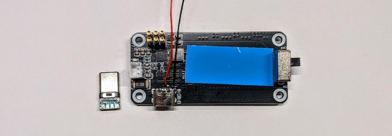
UPS Hat for RPi Zero
For this project, I selected https://amzn.to/3X49IV3 -- that came with “instructions” which was mostly a piece of paper sending to https://seengreat.com/wiki/180 to get the information I needed.
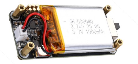
This device is fairly simple. There’s a USB C plug at the bottom to charge the battery, and a set of “pogo” pins at the top that connect to the Raspberry Pi GPIO to provide power. Following the official RPi GPIO pinout, we can figure that the 2x3 pogo pins connect to:
Pin 1 = 3.3V |
Pin 2 = 5 V |
Pin 3 = SDA.1 |
Pin 4 = 5 V |
Pin 5 = SCL.1 |
Pin 6 = GND |
Once first assembled, the RPi Zero 2 W was not turning on. Looking at it more closely, the “pogo pins” were not making any contact with the bottom of the GPIO. These are made to “push” on the bottom of the soldered header pins, and a 2 W doesn’t have headers pres-soldered. I soldered 2x3 pins to ensure the pogo pins had something to make contact with.
I assembled the Raspberry Pi with the UPS Hat and adapted some acrylic plates to protect the various contacts and the now exposed power pins:
Monitoring the Battery
These UPS Hat integrate an INA219, an I2C-controlled IC that monitors voltage and current. This can measure the voltage of the battery as well as the discharge or charge current.
The https://seengreat.com/wiki/180 page links to a “python demo” source code that will get the values from the INA219 sensor. I’ve mirrored this version of the INA219.py here. I’ve noticed that other similar boards link to slightly different versions of the same source. Apparently vendors just copy-paste it around.
Using this is fairly trivial:
$ sudo apt install python3-smbus
$ vim INA219.py
The device address can be either 0x42 or 0x43.
$ python INA219.py
Load Voltage: 4.120 V
Current: 0.307848 A
Power: 1.292 W (idle)
Percent: 100.0%
The device comes with a 3.7 watt/hour battery, and the RPi has a consumption of around 1.6 W when encoding one RTSP video stream. This gives a runtime of about 2 hours. That’s not enough for our needs.
Trickle Charging from Track Power
The battery is excellent to provide continuous power to the Raspberry Pi. Yet we want to charge it while the camera car is running, and what better source of power than the power from the track? In this application, we don’t care if there are any dead spots when the car is running as long as overall it charges more often than it discharges.
The UPS Hat has a USB C plug to charge it. So ideally I want to use that.
The first thing is to realize they provide the schematic so let's use that to figure out the charge circuitry, and maybe get a datasheet for the USB charge controller.
The quintessential question is how close to 5V do we need to be on the USB C port, and whether we need CC1/CC2 resistors.
The schematic of the UPS Hat is here:
https://seengreat.com/upload/file/131%20UPS/Pi%20Zero%20UPS%20HAT(A)Rve1.4.pdf
This is the part we care about:
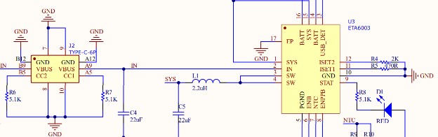
The “Type-C-6P” block is the USB C plug. CC1/CC2 are already connected to the proper resistors. A standard sink device is supposed to have 5.1 kΩ resistors on both CC1 and CC2, which this one does.
We see that VBUS goes directly to an ETA6003 (TI datasheet), which is a “switching Li-Ion battery charger” designed to take a USB input and charge a Li-Ion battery to about 4.2 V. Resistors ISET1 and ISET2 define the desired charge current.
The schematic shows USB_DET connected to the ground, which means the device is in “AC charger” mode and should only use ISET1 to define the “fast” charge current; the 470 Ω resistor on ISET1 means we have a max current of 2 A in “fast” AC charger mode. The 2 kΩ on ISET2 would define a max charge current of 0.5 A in USB mode, and this is not used here as USB_DET is grounded. The values shown above match the datasheet.
In my case, the one spec I need is the input range, which is stated as 4.4 V up to 5.5 V, with an absolute maximum of 6 V. So that’s what we need to present on the USB C VBUS line.
Our goal is to rectify the DCC signal from the track using a full bridge rectifier. On the Randall layout, that will give us a fairly straight 12-13 V DC signal.
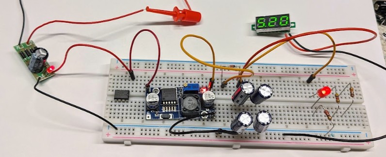
On this early prototype, the AC-DC bridge rectifier can be seen on the left with its smoothing capacitor. I then use a DC-DC Step-Down Voltage Regulator 3-40V to then bring that to 5V. My only problem with this choice is that this type of step-down voltage regulator does not regulate the output voltage to a fixed value, AFAIK, only to a factor of the input voltage.
When running on the track at Randal, the DCC voltage level varies from 12.10V up to 13.5V depending on the NCE booster powering the track. With a step-down voltage regulator like the one above, the output voltage will vary slightly, which is less than ideal. The other main issue is that this DC-DC step-down voltage regulator is quite bulky -- it’s almost half the size of the Raspberry Pi itself. I would like something more compact so that I can fit the entire thing in a small HO-sized car.
Looking in my bin of random parts, the second idea I had was to use a spare USB cigarette lighter adapter:
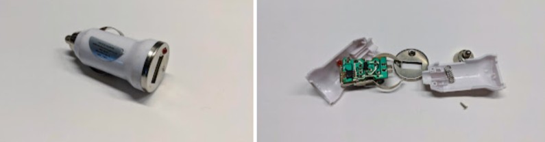
These do have an IC inside that will generate a proper 5V suitable for a USB power, exactly what I need. This is one is a very old “5V 1A max” dollar-store adapter from many years ago, and I don’t use it as it’s not adequate for modern power requirements. Yet the circuit board is fairly small, and I could work it out. The only issue is that these are “rated 1A” but really they crash when you try to pull more than 0.5A out of them. I’d like something that can support a bit more current. And then, wait a second, that reminds me of something… it turns out I already have exactly the right thing for this project:
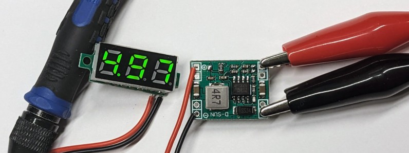
In the first article of this series, I explained how this was a project I started back in 2019. Turns out that back then I had already ordered 2 small stamp-sized DC-DC step-down converters specifically for a 5V output:

The ones I have are fixed for a 5V output. Here’s a similar listing on Amazon with a variable output. These are centered around an MP1584EN, which is a 3A 28V step-down converter (datasheet here). Its input voltage is in the 4.5 to 28V range, and the output voltage is controlled by 2 resistors (either both fixed or with one variable resistor).
Thus we finally have a good solution for our trickle charge scheme:
- We get power from the DCC track.
- We “convert” it to DC using the small AC-DC full bridge rectifier.
- Note that a DCC signal really is a DC signal in disguise with its polarity inverted at a 8 kHz frequency, thus once rectified, we get an almost-ripple-free DC signal. It’s nice to keep the capacitor for smoothing, but it’s not as needed as in a real AC-DC rectification.
- We feed the resulting 12-13V DC signal to the MP1584EN on the DC-DC step down converter.
- We feed the resulting 5V DC signal to the USB C plug on the UPS Hat, which feeds the ETA6003 charge controller.
So I did all this, and it worked as expected:
This fits the camera, the Raspberry Pi with its battery, and a little “power module” with the bridge rectifier and the step down converter, then connected back to the USB C port via a DIY USB C plug. I prototyped some kind of 3d printed supports for the various parts.
There’s just the one detail I totally missed and never thought about: track clearance!
It turns out a USB C plug is “huge” in comparison to the size of my little HO camera car:

I tried on the Randall Layout and I’m clearing some tunnels by a mere millimeter. That’s definitely not acceptable.
OK so fine, time for plan B. Disassemble everything, and solder 2 wires to the GND and VBUS directly on the other side of the USB C port on the UPS Hat:
“We have clearance, Clarence”
Doing it this way, the two wires are still connected to the USB C port, just “on the other side”, the solder side. This is one of the “power only” USB C female ports so luckily it has only 6 pads. Still they are fairly tiny and it was a bit of a PITA to solder my wires. I’m using 28 AWG which is “small” yet looks huge compared to everything else on that board.
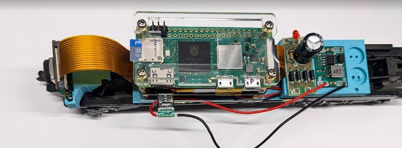
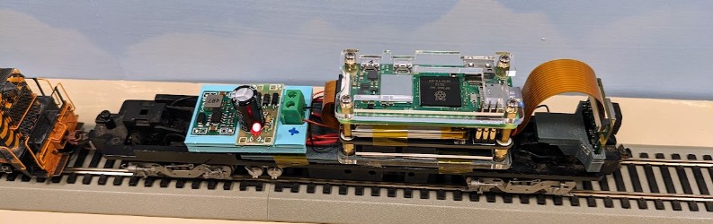
Since I had to disassemble everything, I 3d-printed another version of the supports for Raspberry Pi, camera, and power module, and here’s the final version once reassembled:
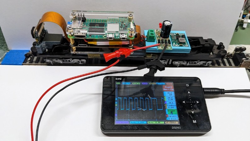
The square wave signal is the DCC signal as measured just before the full bridge rectifier, by the way.
This time there are no wires for power outside of the body. They connect to the green 2-position terminal and go directly under the RPi.
Camera Control Software
I’m keeping the software to a minimum on this project.
All the scripts for the Raspberry Pi are in this https://github.com/model-railroad/cam-car repository:
- Video Streaming Service:
- This uses a basic systemd picam-stream.service to start the picam-stream.sh script when the Raspberry Pi boots.
- As explained earlier, this uses the rpicam-vid to capture the video and streams it using cvlc.
- Battery Monitor Service:
- This uses a basic systemd picam-power.service to run a battery monitor script picam-power.sh.
- When the battery goes below 50% and it is not being charged, we initiate a system shutdown to save power. There is no facility to turn it back on -- that’s up to the user to do that.
- batt_level.py is a basic tweak to the INA219.py program to dump the battery state in a format that is easier to grep in the bash script.
- At the expected rate of discharge, the Raspberry Pi would have to be running for one hour without power for this to happen.
The video is accessible at the network stream URL rtsp://zero1.ggmrc:8554/stream1 on the layout’s internal wifi network.
On the viewer side, I’m using my own TCM Android app on an Umidigi G1 10-inch tablet.
With a bit of experimentation, I found these parameters work well:
- rpicam-vid: video 640x360, at 4000kbps and 20fps.
- TCM: configure FFMpeg with “format=rtsp” and “rtsp_transport=udp”.
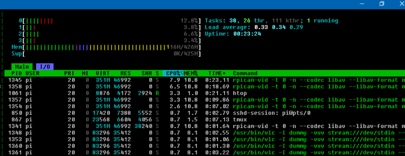
When running, the Raspberry Pi Zero 2 W generally runs at 10~15% CPU max.
And this final result:
is that’s what I successfully ran at the Randall Museum today, almost one month after I started this project.