NCE Switch-8 and PFM Fulgurex |
2017-01
In this article, I'll describe how to add DCC control to a PFM Fulgurex turnout motor using an NCE Switch-8.
1- Overview of the PFM Fulgurex Turnout Motor
2- Overview of the NCE Switch-8
3- Preferred Method: NCE Dual Relay Board
4- DIY Method: Using our own DPDT Relays
5- Alternatives: Transistors or L293D
6- Other Stationary Decoders and Cost Comparison
1- Overview of the PFM Fulgurex Turnout Motor
"It's the 60s, baby".
The Fulgurex is an old limited-switch slow-motion turnout motor (a.k.a. point motor for our British friends).
In modern layouts that I've seen, people use Tortoise-brand slow-motion motor turnouts. When working on the Randall Museum's layout built by the Golden Gate Model Railroad Club in 1961, I found out about half of the turnouts on the mainline are powered by Fulgurex motors. It apparently used to be the norm on the layout before it was converted to DCC when some members patiently replaced half of them by Tortoise motors.
This is what a Fulgurex motor looks like:


The inscription on the back reads "Fulgurex / Pacific Fast Mail".
Historical side note: PFM was a company from Edmonds, Washington. They were reputed for their quality brass steam engine imports, their turnout motors, and the Sound System II (which allowed for steam engines with synchronized chuff sounds, something way in advance for the late 70s). Their first catalog is from 1956 and the last one is from 1982.
I located the original user manual in the club archives and scanned it:
bitbucket.org/randall-railroad/documentation/src/master/hardware/PFM Fulgurex User Manual.pdf (PDF)
This site http://www.clag.org.uk/fulgurex.html provides some additional details.
The gear mechanism pushes the point and the contacts will stop the motor. They use roughly 200 mA in motion and none at all once the motor reaches its position.
By contrast, a Tortoise uses 4 mA during operation and 15-16 mA at stall according to the Circuitron pamphlet. That difference is going to be important below.
The layout has about 30 Tortoise and about 23 Fulgurex still in working condition. Not bad for something that was installed in the 60s and has been running for more than 50 years.
2- Overview of the NCE Switch-8
The NCE Switch-8 is a DCC-controlled board to drive up to 8 turnout motors. It accepts an auxiliary card, the NCE Button Board, to connect local buttons.
I originally chose this accessory decoder because I need to control around 16 turnouts and the local control is done using non-momentary rotary toggles, which the NCE Button Board is supposed to support (but it turns out it doesn't, as I explain here).
Here's what mine looks like:

Power is provided from the DCC bus via the 2-pole terminal block on the top right or from a DC power supply via the barrel plug at the top in the center. Most of the time we'll connect both -- the DCC bus is useful when programming and the DC power is what we really want to use for powering our turnouts -- because when our train will run against the turnout and short the DCC power district, we still want the board to be powered so that we can rectify the turnout position!
NCE has two of these boards:
- The NCE Switch-It drives up to 2 turnouts.
- The NCE Switch-8 drives up to 8 turnouts.
By default, an NCE Switch-It or a Switch-8 will drive Tortoise motors just fine but not the Fulgurex motors.
The reason is that according to the specs, the Switch-8 output can only deliver up to 40 mA. That's enough for the Tortoise which only needs 4-15 mA (even 2 of them in crossover) but not at all for a Fulgurex which needs 200 mA.
Trying in practice… nothing happens. The Fulgurex just doesn't move an inch.
Can the Switch-8 really output only 40 mA? Well, we just need to look at the board to figure it out.
As I said before, one of the things I like with the NCE boards is that they are fairly simple. And in this case, one can clearly see the four LM324A chips that connect directly to the outputs.
By tracing the board, I made this quick back-of-the-envelope drawing of the circuit for each output:

(And yes, that is really literally drawn on the back of an envelop :-))
The LM324A is a 4 ampli-ops chip. When checking the TI specs, each output is limited to 60 mA.
So that's what we got to work with. I'll stick to the 40 mA figure from the NCE documentation. Clearly that won't drive a motor that wants 200 mA.
Let's look at alternatives to drive the Fulgurex.
3- Preferred Method: NCE Dual Relay Board
I'm going to remove all suspense and point out first what I think is the best solution that actually works painlessly.
NCE sells the "Dual Relay" Board with 2 relays which is perfect for the task. They even point out the connection diagram in the doc, which can be seen below -- the black & white part on the left and middle is straight from the NCE Dual Relay documentation; they show it with a Switch-It and it works the same way with a Switch-8:

The way this works is very simple: the A/B output of the Switch-8 for the selected turnout drives the relay's coil. Each relay is an SPDT. The DC power for the turnout goes in the middle of each 3-pole terminal block. The outputs are connected in a crossover configuration that inverts the polarity when the relay is closed.
Note that in this mode, we'd be using one NCE Dual Relay board for each Switch-8 output that needs to control a Fulgurex. If we're driving a crossover, we can still use a single NCE Dual Relay board for the two crossover turnouts.
4- DIY Method: Using our own DPDT Relays
Another sensible alternative is to use our own relays.
The NCE Dual Relay is nothing more than a DPDT relay, and we can trivially roll our own.
I'm going to digress in a bit of a philosophical argument here. When it comes to electronics, especially for train layouts, there are often two valid approaches: do-it-yourself or buy off-the-shelf components. These days there are tons of off-the-shelf components to choose from. On the other hand with Arduinos and the like, it's increasingly easy to just make our own.
There are many pros and cons, but essentially it boils down to confidence and cost. If you're not versed in electronics, it's best to just buy something that will work. On the other hand, if you like DIY electronics you may be tempted to just do your own electronic circuits "because you can" and in this case I look at two things: future maintenance and cost.
Future maintenance depends on how and where this is going to be used. For my own stuff at home, I have no problem creating custom solutions. Often creating the electronic board is the goal of the game itself. However in my case I'm looking at a solution for a museum where I have no control. In the future, I hope this will be maintained by someone else, and that person might not be an electronics expert or even wannabe. If they find a relay burned out and needing to be changed, would they rather have to try to understand a custom-made board and recreate a new one, or would they rather just go online and buy an already made component that they can simply swap by unscrewing a couple terminal blocks? The latter seems the most logical choice.
As for cost, I think people often get it very wrong. NCE sells their Dual Relay board for about $20. Some folks may complain about the cost, on the other hand I think it is a very reasonable price for what is essentially a niche electronic device. A DIY solution would require a relay, which is going to be around $4-5; ideally it would need a flyback diode; then it needs a PCB to be designed, printed or manufactured, and finally the thing has to be assembled and all that time has a (hidden) cost. The raw parts may be well cheaper than the NCE’s $20 board, yet the end cost when accounting for the cost of tinkering and time spent is well above that.
In the end, to control just a few Fulgurex motors, I'd go with the NCE Dual Relay boards. For a large number, I'd go for custom-made boards. I purposely did not specify how many is "a few".
In my case it's very arguable because I need two of these with 8 outputs each, which is on the "few" side. I can create a design with 8 DPDT relays and terminal blocks that is more compact than using 8 NCE Dual Relays next to each other. Cost isn't going to be much different since I just need 16 of everything, so there's no saving on bulk electronics purchase. Eventually the "future maintenance" aspect is more important and I'll use NCE Relay Boards just for that aspect.
Yet, I did buy one relay just for the sake of trying it out -- and as an excuse to write this article.
After looking on Mouser and Digikey at various relays, I realize there's a huge selection. So let's spec the relay:
- I need a DPDT -- dual pole, dual throw, a.k.a. "2 form C".
- Not latch-type.
- Coil voltage is around 12 V DC and it needs to use less than 40 mA. That seems to fall in the "high sensitivity" category, and these seem to use around 10-20 mA for coil current, which is very appropriate.
- In my case the output of the Switch-8 is between 10 and 11 V. Most 12 V DC coil relays seem to have a turn on voltage of 9 V, which will work fine here.
- On the load side, I need 12 V DC at 200 mA and all of these will trivially accept way more than that.
Looking on Mouser or Digikey will show a basilion of potential relays matching these specs so I'm not going to list a specific one. But you need to look carefully. For example, let's take the Omron G5V-2 relays (G5V-2 datasheet here as PDF). The G5V-2-12V has a coil rating of 41 mA at 12 V, 288 Ω, which is not suitable for the 40 mA max of the Switch-8 output. Instead one would have to use their high-sensitivity version, the G5V-2-H1-12V, which has a coil rating of 12.5 mA at 12V, 960 Ω.
For testing, I picked a random through-hole sealed model TRS-12V-SA-L20 from Amazon. After finding a vaguely similar looking datasheet from RU, I found the reference means:
- 12V: Coil voltage, 12 V DC
- L20: High sensitive (sic), coil power 200 mW.
200 mW at 11-12 V DC will use around 15-20 mA, which is perfect for what I want.
And also these sealed relays are very tiny. They don't have sockets to be replaced though as they are through-hole for PCB soldering.
Once mounted on a quick experimentation board, my relay looks like this, below.
Compared to the NCE Dual Relay, I could get a much more compact board if I want 8 of them in parallel.


The diagram describes how the relay is to be wired.
The relay control is wired between the GND of the Switch-8 and the corresponding B output of the desired turnout. Doing it this way means the voltage on the coil will be either zero or positive -- the control will never be a negative voltage, which works best for the relay I was using. Yours may vary.
Not shown here and not present on my quick prototype board, a flyback diode should be wired between the two relay control pins.
The outputs of the DPDT relay are wired using the traditional crossover which inverts the signal. The two NC (normally closed) outputs drive the 0/12 V to the output as-is. When the relay is activated, it inverts the outputs to present a 12/0 V output to the Fulgurex, turning it in the reverse position.
5- Alternatives: Transistors or L293D
That brings us to the second option, transistors.
We have something that can output up to 40 mA and we need to send up to 200 mA.
Transistors amplify current, which is exactly what we want here.
However transistors are a bit like diodes and only work in one direction, so we need 2 transistors per wire, 4 transistors total for one turnout. This design is well known in the literature and called an "H Bridge" and there are readily made components that do everything we need. There's a lot of literature on H Bridges out there; if you're not familiar just have a look at https://www.wikipedia.org/wiki/H_bridge to get started.
When I asked around, I was told "use an L293D, it will do what you want".
Always take such forum advice with a question mark. Because maybe it doesn't. Let's look into it.
The L293D is a "Quadruple Half-H Drivers". Datasheets are here:
The "D" means it can drive up to 600 mA per output. We want 200 mA so that's enough.
We need 2 drivers for each Fulgurex (one for each wire) and since the L293D has 4 drivers, we can drive 2 full turnouts.
The L293D has 2 voltage inputs: one for control (Vss for logic) and one for the drivers (Vs, what gets output). Since both support a range of 4.5 V up to 36 V, we can use our 12 V DC supply on both sides.
Here's our wiring diagram:
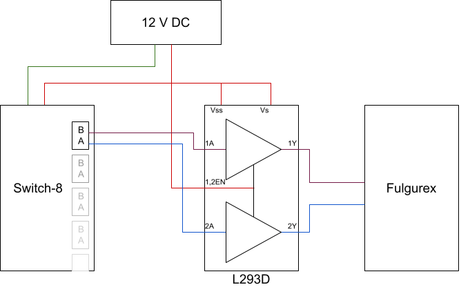
So will that work? Well, on paper, we actually DON'T want to do that without looking into it in more detail.
There's a little trick in the datasheet: Vss (the logic voltage) can be up to 36 V but Vi and Ven (voltage for inputs and enable) are actually 7 V max. We cannot should not put anything past 7 V on inputs 1A, 1,2EN and 2A. Oops.
The Switch-8 will deliver one less volt than its input. With a 12 V DC supply, we would be supplying around 11 V, which is more than the 7 V supported by the L293D. In my case, mine gets about 11 V on the supply and about 10 V on the A/B outputs.
That could be worked out in a number of ways:
- The A/B voltage can be lowered using diodes. The typical 1N4001 will drop 0.7 V, use as many in series as needed.
- One of these could be a LED used to drive an indicator panel at the same time; be sure to check the voltage drop of your LED as it depends on the color.
- For LED or diodes, consider having a resistance to limit the current through the diodes.
- Use two resistors in series to create a voltage divider and arrange for the middle voltage to be lower than 7 V.
- Lower the DC supply of the Switch-8 to its minimum, which is documented as 8 V DC (manual says 8-15 V DC on barrel plug). In this case, we should get about 7 V on the A/B outputs, just within the spec of the L293D.
- All or a combination of the above, as needed.
Bottom line is that this is a potentially workable solution, given the caveats above.
6- Other Stationary Decoders and Cost Comparison
As indicated above, I originally choose the NCE Switch-8 as an accessory decoder based on these four principles:
- That I was dealing with Tortoises, which the Switch-8 supports.
- That I wanted to control around 45 turnouts total, so having a card supporting 8 at once was very beneficial.
- That I would connect to a local panel composed of non-momentary rotary toggles, which the NCE Button Board is supposed to support (yet in practice it doesn’t).
- That the board is not primarily powered by the DCC bus (shorts on the DCC power district should not prevent a turnout from being rectified).
Two of these principles were false. Turns out that layout wasn't only using Tortoise but also Fulgurex, which I didn't realize at first, and it took a bit of research to identify what these things were. It also turns out that the NCE Button Board does not work with non-momentary contacts.
The cost of the NCE Switch-8 is $70 ($8.75 per turnout when driving Tortoises).
Each NCE Dual Relay board is $20 so that brings the cost to up to $28.75 per Fulgurex.
Here are other options that I considered to control the Fulgurex from DCC. I did not try most of these, I'm just listing these for the sake of completeness:
- The NCE Switch-Kat ($25). This drives "one Kato Unitrack and LGB remote control turnouts". The documentation indicates the outputs are rated for up to 1 A, which will work with the 200 mA usage of the Fulgurex. It has inputs for local momentary contacts (push-button). It is powered only by the DCC bus.
- The NCE Switch-It ($30) is designed to drive up to 2 Tortoises and thus can't drive the Fulgurex directly. That's $15 per turnout, and if we add the NCE Dual Relay, that brings the total to $35 per turnout. It has inputs for local momentary contacts (push-button). It is powered only by the DCC bus.
- The CML Electronics DAC10 or DAC20 (now called Sig-naTrak DAC20, £65) controls up to 8 turnouts. The documentation does not clearly indicate the max output current, although there's one forum post where someone indicates he can drive 3 Fulgurex with one board with no other details. The documentation does not clearly indicate whether non-momentary contacts would be supported (it mentions toggles and edge-based control so maybe it would?) And finally the documentation is a bit confusing on whether accessory power can be done from DC instead of the DCC power bus (the board has both inputs but the aux power input is only mentioned with twin-coils turnouts).
- The Digitrax DS64 ($60) drives up to 4 turnouts ($15 per turnout).
- It has a clear auxiliary power input -- with the caveat that it’s either all-DCC (power + command from DCC) or aux power + LocoNet. Update 2019: one cannot do like on the NCE Switch-It 8 and use external aux for power yet get commands from the DCC. That is just not supported. Thus in my usage case, it is powered only by the DCC bus
- It supports local inputs but does not clearly indicate whether non-momentary inputs are supported or only momentary are expected. The documentation does not precise the max current on outputs.
- Update 2019: I do not recommend the Digitrax DS64 to drive a PFM Fulgurex. It works “sometimes”, e.g. if the motor does not use too much current. When the motor uses too much current, the DS64 voltage output drops and it just can’t drive it anymore, which leaves one with a turnout that is sluggish (at best) or won’t turn (at worse).
So these are the alternatives I found. I have no idea if they are others. The NCE Switch-Kat could have been promising except it does not support an alternate DC supply and does not support non-momentary contacts. The DAC20 might be a plausible choice. Having tried it, the DS64 is clearly not a suitable choice (it’s hit or miss).
~~
~~