Presentation & Automation of the
Randall Museum Model Railroad
Last updated 2024-08, by Raphaël Moll
This document gives an overview of the model railroad located in the Randall Museum in San Francisco. It first describes the “original” state of the layout and then follows up with the technical details of the automation of the layout, as well as the on-going changes and maintenance. Disclaimer: A lot of the content in the first chapters is based on personal observations trying to decipher the existing layout and provide documentation where little or none exists, and as such are entirely based on my own discussions, observations and understanding -- and many times lack thereof. However, the sections on automation and maintenance are authoritative and are updated on a regular basis to reflect the current state of the layout.
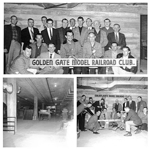
The model railroad was built by the GGMRC (the Golden Gate Model Railroad Club), starting in 1961. It is located in the basement of the Randall Museum in San Francisco, CA.
1.2- Model Railroad Design Impact
4.4- East-West, Running Direction, Polarity, and Common-Rail
5.2- Building Illumination / Lights Power Supplies
6.2- Block Power for Yard Panels
6.3- Front Yard toggles on Mountain and Valley Panel
6.4- Block Power Selection for Mainline Control Towers
6.5- Valley DC Power Selection
6.8- How Not to Wire a DCC Layout
8- Stockton Station & Stockton Yard
9- Stockton Industrial Area & Dow Freight Sidings
10.2- Update to Block B905 & Turnout T110
10.4- Fairfield Grade Crossing
13.2- Richmond Industrial Yard
16- Changes from GGRMC to Randall
16.1- DCC Conversion for Automation
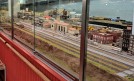
16.2- The Window Barrier and Fascia
17.1- Initial Automation Proposal (2016)
17.2- Revised Automation Proposal (2017)
17.3- Updated Automation Proposal (2018)
17.4- Further Automation Proposal
19.1.3- Mountain Panel 1 DCC Block Detection
19.1.4- DCC Block Detection on Other Panels
19.2- Turnouts conversion to DCC control
19.2.1- Existing turnout implementation
19.2.3- DCC implementation details
19.2.4- To convert a Turnout to DCC using NCE Switch-8
19.2.5- Somewhat Correcting the NCE Button Board
19.2.6- To convert a Turnout to DCC using Digitrax DS64
19.3- List of DCC Controlled Turnouts
19.4.1- Single Automation Toggle (2017)
19.4.2- Dual Automation Toggle (2018)
19.4.3- Update to Automation Toggle (Mid 2018)
19.5.1- Activation Buttons (2017)
19.5.2- Activation Buttons, Missed Events (2018)
19.5.3- Motion Sensor (Mid 2018)
19.6- Computers & Infrastructure
20.2- Phase Exploration (2017)
20.5- Follow-up Maintenance and Work (2018)
20.6- Follow-up Maintenance and Work (2019)
20.7- Follow-up Maintenance and Work (2020)
21.2- Phase Exploration (2017)
23- Ongoing and Future Projects
23.0- Pending Work on the Layout
23.2- Project: More Labels & Documentation for Operators and Visitors
23.2.1- Labels & Documentation for Visitors
23.2.2- Labels & Documentation for Operators
23.3- Project: Power for the Branchline
23.4- Project: More Blocks & Turnout Control for Branchline
23.5- Project: Power for Stockton Passenger Station [done]
23.6- Project: Turnout Control for Stockton Passenger Station
23.7- Project: Block Detection for Stockton Passenger Station
23.8- Project: Power for Fairfield
23.9- Project: Automation for Fairfield
23.10- Project: Fix Mountain Panel Toggle Panel
23.13- Project: Mountain Panel
23.15- Project: Access to Richmond / Napa from Mountain [done]
23.16- Project: NCE AIU01 to Monitor EB1 Circuit Breakers
23.17- Project: Update Building Lights to LEDs
23.18- Project: Workbench with NCE PowerCab, Digitrax PR3, LokProgrammer
1- Model Railroad Design
1.1- Overview
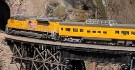
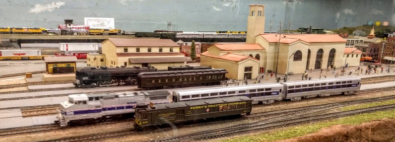
The design of this model railroad may look peculiar and confusing to first time observers, with trains going into tunnels and emerging somewhere else in the opposite direction.
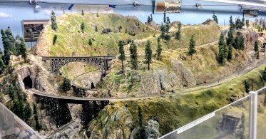
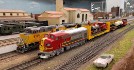
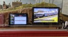
Here’s what visitors see when they enter the room:
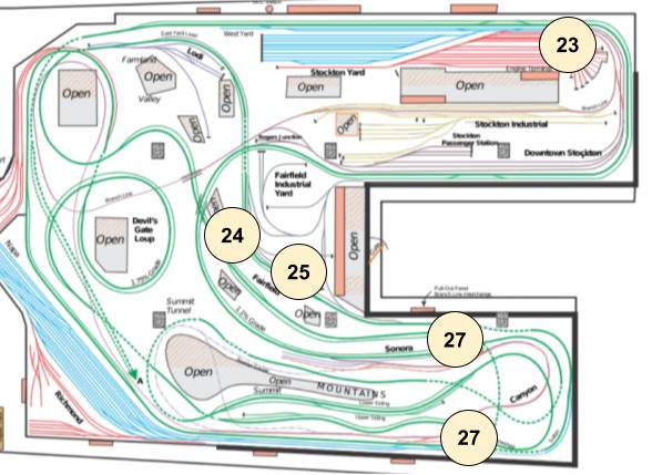
And here is the track plan, which shows the multi-level mainline looping over itself repeatedly:
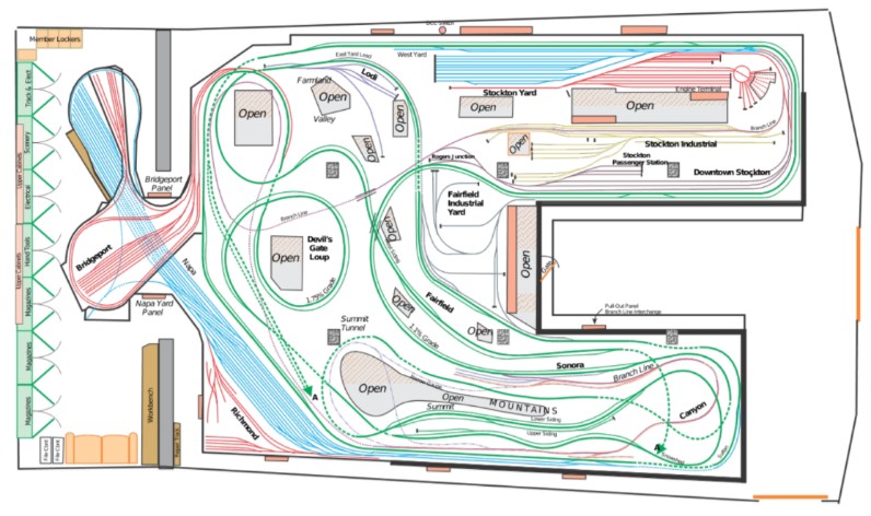
The track forms a mainline, which is sometimes a single track and sometimes a double track. There is a branch line and several yards. As it was common in this era, the layout is controlled by two main control "towers" -- the Valley Tower and the Mountain Tower. These panels concentrate all the blocks and turnouts controls for the corresponding sections of the layout. Each yard has its dedicated block and turnout control panel.
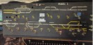
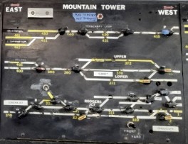
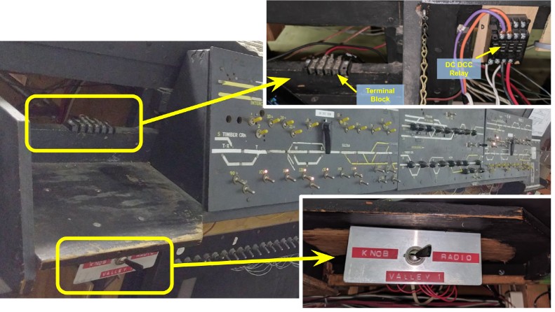
Operators are usually very confused at first. Here’s what one of the two main control panels looks like:
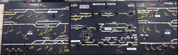
The Mountain Tower panels (block control and turnout control)
Although it all seems confusing, there is some definite logic and rationale in the layout plan and the control panels.
There are two major power districts (valley or mountain) which can be operated using two different throttles (power supplies at different levels). Each "tower" (mountain or valley) is actually composed of three sub panels, as pictured above: one turnout panel and two block control panels (Valley 1 vs 2, Mountain 1 vs 2) which duplicate each block control, thus allowing a specific block to be powered either by throttles from side 1 or side 2 or turned off. At some points mainline blocks also had occupancy lights.
The yards have their independent throttles and tracks leads in and out of the yard have a power selector to dictate which throttle is powering an engine entering or leaving a yard. Later radio-controlled DC boosters and MRC power supplies were added.
This always seems confusing to the non-initiated so I’d like to introduce a bit of background on why the layout was built that way.
Layout design has naturally evolved over the years. This layout is built using what was the “state of the art” back in the 60s. The natural tendencies for layouts back then was to try to cram the most track in a given space. A longer mainline makes people who like to run happy. The easiest way to achieve that is to have multiple levels, with the track looping on itself.
In the pictures above, the “mountain” area and the “devil gate loop” are good examples of that. On the mountain side the track goes up through three levels, on the other side it goes down through two loops. This looks visually confusing as trains enter a tunnel at the middle of the mountain at one level and go out of the mountain at another elevation in the reverse direction. As an anecdote, it is worth noting that this design style fell out of favor in the 80s in favor of more linear layouts with elevation being taken care of using helixes behind the scene -- which has brought different design issues.
One interesting design consideration is that when I joined the GGMRC in 2014, everyone was running the mainline clockwise, that is starting from the Stockton Yard towards the Stockton Station then to the Mountain/Summit then going down through the “devil’s gate” loop (which is obviously build to look like the well-known Tehachapi Loop in California). However I was told the layout was originally designed to run counter-clockwise and the reason they choose to run clockwise is that the mountain is a 1.1% grade going up followed by the loop with a 1.75% grade going down, which is much easier than the reverse. Personally from an operational perspective I see the layout as being able to run both directions at once with clear sidings for meets and potential for helper units being added and removed for the long grades.
Let’s consider the electrical and control aspect. The layout obviously started as DC (non digital) control. One bit of background explanation is useful here: on a DC layout, the trains are powered by the voltage applied to the track. Typically one transformer is connected to the track and varying the voltage controls the trains speed -- all trains powered by the same transformer all go at the same speed at the same time, they cannot be individually controlled. This is clearly an issue on a large layout like this where there would be multiple trains running at the same time, possibly in reverse direction.
To solve that issue, the mainline is cut into blocks that can be independently turned on or off. One additional complexity added here is that they have not one but four independent power sources -- two power districts (the two Towers) which each have two “cab throttles”. On the Mountain Tower picture above, the “Panel 1” on the right and the “Panel 2” on the left can be used to decide if a given block is powered by the throttle 1 or the throttle 2 or neither.
Yards have their own control panels with their own separate “cab throttle” power supply. A switch is used to decide whether the yards are powered from throttle 1 or 2 (to enter and leave the yard) or by the yard throttle (when inside the yard).
Thus two operators could run trains on the Mountain area, with two different operators on the Valley area, then each yard could have its own operator.
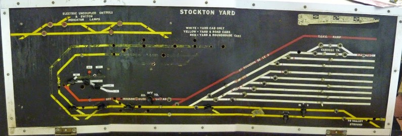
The Stockton Yard panel (apologies for the low quality stitching)
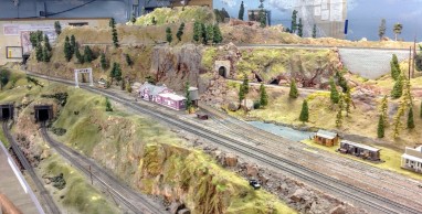
To understand the nature of the confusion in operating this, let’s look at this picture:
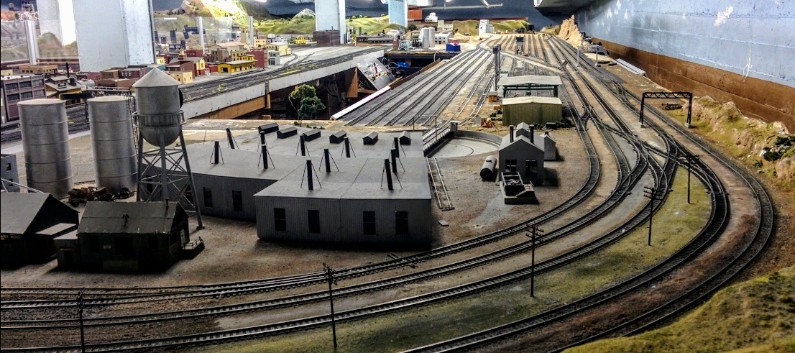
This part of the layout is actually controlled by 4 distinct control panels, each located at different places. Here’s the same image with indications of where the control panels are and which area they operate:
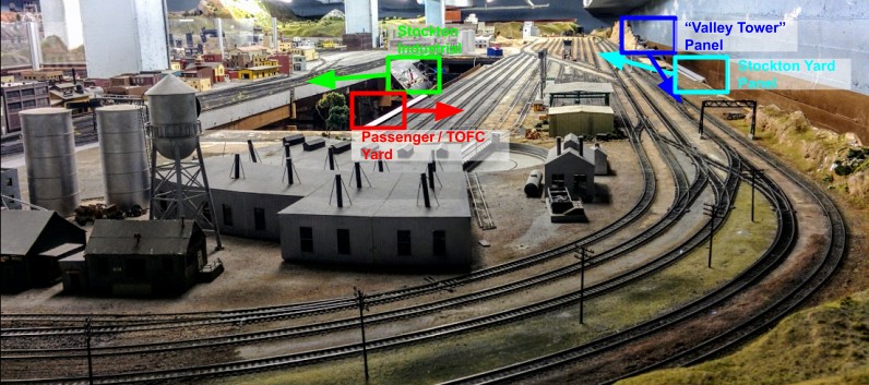
The mainline is on the very right, controlled by a “valley tower” control panel in the middle behind that mountain on the side of the layout (dark blue); the main Stockton yard is composed of two sections controlled by two separate panels (light blue and red) and the Stockton Industrial yard is controlled by another panel (green). One needs to crawl under the layout to reach the two yard panels denoted in green and red below.
Another issue worth pointing out is that the “Valley Tower” control panel, denoted in dark blue above, also controls mainline turnouts which are located on the very opposite side of the layout, out of visual range.

The following schema represents the track from the picture above (seen from the left). It shows which track is controlled by which yard panel:
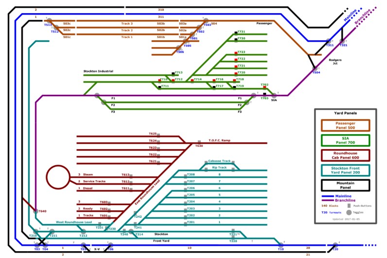
One leading confusion is that the panels are old and quite frankly poorly documented. The schema above was made to understand the logic behind it and especially to understand what happens at the boundaries.
Of note, the DFS is incorrected mixed with the SIA on this drawing as I did not understand the difference between both at the time. This topic is further addressed in the DFS/SIA section below.
It is worth noting that although the panels have blocks numbers, these have no matching visible indication on the layout. Similarly, turnout toggles offer no way for one to directly match a specific button to a turnout on the layout. The only link is the track plan on the panel, which some people find obvious and others find cryptic.
1.2- Model Railroad Design Impact
From an engineering and operational perspective, this is quite a good scheme. There is both logic and complexity. For example, taking a train from the mainline to the passenger yard next to the roundhouse involves no less than three panels, located at different places. That’s a lot of operational potential and also a lot of busy work. The downside is that it involves quite a bit of crawling under the layout to reach some of these panels. It has been observed that most club members did not care for that complexity, which means few would look for such operations or be extremely reluctant (and annoyed) at it.
The same goes for running in opposite directions on the single-track mainline. On the prototype (“real”) railroad, it involved careful coordination (typically with timetables and hand-delivered orders) to have trains that can meet and stop at sidings. The same would be needed here, with operators coordinating with each other and using the sidings available via the Mountain Tower control panel or the Valley Tower control panel. The lack of labelling and the lack of easily identifying which turnout toggle controls which physical turnout means that a lot of operators would just randomly flip a toggle to see if they actually triggered the turnout they wanted. We have seen every operator make mistakes when switching, including seasoned operators. This is not a sound operating principle.
Consequently what most members did was just stick their trains on the mainline and run it as a unidirectional loop with no operational variety whatsoever. Everybody’s running long trains one following each other.
Another issue is that this layout was also an “exhibit” for the museum hosting it. Every Saturday, visitors would come in and expect to see trains running, most visitors being kids who want to see trains running around, which works well on this complex looping layout design. This compounds the issue as operations are not something exciting to look at and falls in disfavor of simply running trains on the mainline as a continuous loop. On the plus side, since the layout loops over itself, even multiple trains all running in the same “logical” direction look like they are going in different directions visually so it does give a greater sense of variety than there actually is.
Historical anecdote: this kind of layout is well designed to have one manned dispatcher in each control tower. Two operators can run on the mainline in reverse of each other and coordinate meets with the tower dispatcher. Since each operator would use the wired “throttle” connected to the tower, they would be next to each other and be aware of the area in control. Eventually starting in the 70s/80s, this layout design started to fall in favor of “walk around” cab designs in which small control panels are scattered on the fascia of the layout, directly facing the turnouts they control. This makes it trivial to understand which toggle controls which turnout. Plug-in throttle or wireless systems mean an operator can literally walk around the layout following its train, instead of relying on a central dispatcher. A walk-around design also greatly simplifies electrical wiring as there is no longer a need to run long cables from a central tower to remote parts of the layout.
As indicated above, current practice is to have trains run in a loop in a clockwise running direction -- from right to left when looking at the mainline for example in front of the Stockton Passenger Station. West would be on the right, with trains running towards East, on the left. Allegedly the layout was built for running in the reverse direction (from East to West) and this practice changed later to make the grade in the “Devil’s Gate / Tehachapi loop” easier as the grade is fairly steep uphill. (One would argue that maybe the original intent was to mirror the prototype and thus force operators to use helper engines, providing more operational variety, whereas the current setup results from a desire for erasing any kind of operation and just run the layout as a naive mainline loop, but that’s not a discussion for this document.)
2- A Brief History
This is a work in progress. Some events are approximate -- all dates that appear here are based on some kind of visual evidence (some panel’s inscription, older picture, older document) or blog post.
1961: The GGMRC (the Golden Gate Model Railroad Club) starts the layout in the then unused Josephine Randall museum basement.
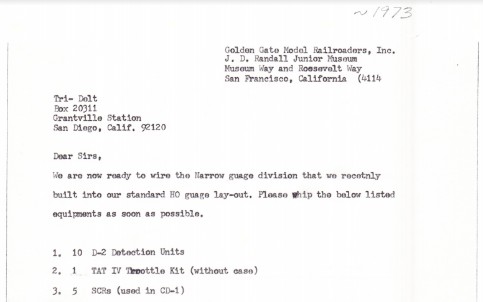
1967: Design documents for Branchline referencing a 1967 “Transistor Throttle” from Tri-Delt.
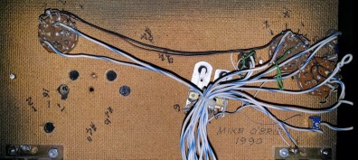
1990-91: Branchline is upgraded or modified with new panels.
2000(?): Some members vote for/against an early DCC conversion.
2009: DFS tracks added to the SIA.
2013: DCC added.
2014: Museum announces to the GGMRC they need to destroy their layout. Hilarity ensues.
2015: Museum forcing a renegotiation of lease contract, ends up on impasse due to inflexible one-sided demands. Layout maintenance by long-time members is mostly inexistent.
2015, December: After months of painful and pointless negotiations, the remaining GGMRC members give up and officially donate the layout to the museum. The actual GGMRC association (GGMRA) is neither officially dissolved nor active after that.
2016: Randall Museum under renovation, and stated to reopen “early 2017”. No access to the train room is possible for most of the year. Two members propose a compromise to move forward, with yours truly to carry the work of maintaining the layout and at the same time propose some automation as the museum wants it.
2017: Randall Museum still under renovation. Limited access to the train room is possible. Automation starts to take shape using the RTAC software.
2018: Randall Museum reopens in February with a working, automated “train exhibit”.
2019: Ongoing repairs to support Saturday runs, rehabilitation of the train yards; automation gains a reputation for being solid and reliable.
2020: Randall Museum closed for COVID-19 Lockdown in March.
2021: Randall Museum reopens in October. Saturday running, yards, and automated trains are fully operational due to diligent ongoing maintenance.
2022: The GGMRA (a.k.a. GGMRC association) is allegedly officially dissolved.
2023: RTAC software version 2 is deployed.
A collage of photographs found in archives, labeled 1961.
Narrow-gauge Branchline is “ready to wire” in 1973.
The Branchline You Bet panel, with inscription “Mike O’Brien 1990”.
3- Glossary
This is a glossary of terms used in the Manual for the Randall Museum Staff to explain what is known as the “Randall Train Room” -- these terms are referenced in this staff-specific documentation as well as on labels in the train room. The names are kept voluntarily non-technical (where possible and appropriate) in order to be as easy to understand by the staff as possible. As such, they may differ from what a model railroad technically-oriented enthousiast may expect.
Name / Label |
Pictures / Description |
|
Train Automation |
Computer program that automatically moves the trains on a timer during museum hours, based on detecting visitors' motion. It turns off automatically at 4:50 pm. |
|
Train Layout |
In Model Railroading terminology, a “layout” denotes the whole thing -- the miniature decor, the tracks, the trains, etc. |
|
Pullman Car |
Exhibit with the locked cabinet covering the lights and layout & outlet power switches. |
|
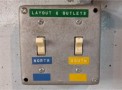
“Layout & Outlet” Power (main switches) |
The main switches at the entrance. The “Layout & Outlet” Power must be the first on and always the last off. |
|
DCC Power Switch |
The DCC Power Switch is located under the layout, next to the Automation Computer. It is located in a gray box protected by a gray cover. |
|
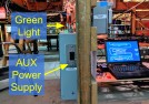
Auxiliary Power Supply |
A power supply located to the right of the Automation Computer. |
|
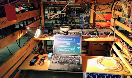
Automation Computer |
The computer under the layout, next to the DCC Power Switch. It runs a custom-made program that orchestrates the whole train automation. |
|
Name / Label |
Pictures / Description |
|
DCC Command Station |
An electrical device that provides power to the trains. It is located behind the Automation Computer. |
|
Valley Panel 1 |
The large black console with toggles to the right of the Automation Computer. |
|
Automation On/Off Toggles |
The two toggles that enable/disable automation, located on the “Valley Panel”. |
|
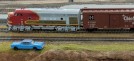
Mainline |
The main track where the Passenger and the Freight train runs. They share the track so only one can run at the same time. |
|
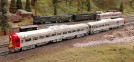
Branchline |
The track where the 2-car silver train runs. |
|
Passenger Train (runs on mainline) |
Currently that’s the yellow train. Color may vary as we change cars/engines. Parked next to the station. |
|
Freight Train (runs on mainline) |
The one next to the yellow train. Composition may vary over time. Parked next to the station. |
|
Branchline Train |
The 2-car silver train running on the branchline, by the mountain side. Train may vary with time. |

Name / Label |
Pictures / Description |
|
Mountain Side |
The right side of the layout with hills and slopes. It depicts California's Sierras. |
|
Valley Side |
The left side of the layout that is mostly flat, and contains the large city with a station and the building on fire. It depicts California’s Central Valley. |
|
Stockton Station |
The main large station located on the left side of the layout. The two Mainline trains (Passenger & Freight trains) are normally parked in front of it. |
|
Video Computer |
Located by the entrance, it displays a loop of videos of model trains filmed on this layout. |
|
“Engine” vs “Car” |
Different parts composing a train. Typically the “engine” is the first part (with the motive power), and “cars” are the ones behind. |
|


4- Electrical Design
“It seems to run on some form of electricity.”
4.1- DC, DCC and DCM
As stated above, the layout did start as a DC layout. Also called “analog”, in “direct current” mode trains are powered via the track and the voltage applied to the track directly dictates how fast the train motors go. Any engine placed on the same piece of track receives the power and thus runs.
Since the 2000s’ and 2010s’, trains layouts have started switching or being built exclusively for DCC, “digital command control”. In this scheme, model trains are still powered by the track and the track is always at full voltage. However each engine is equipped with a microcontroller (called a “decoder”). Each engine is given a number and the microcontroller listens for digital commands sent via the track and only accepts the ones for that specific number. Users operate the trains by using wired or wireless remotes (called “cab throttles”) which send run commands to a specific engine number.
A few years ago the layout was converted from DC to DCC. I could not find any specific documentation on the technical implementation of such, so the following is entirely based on my own discussions, observations and understanding -- and many times lack thereof.
The layout was not just “converted to DCC”, it was made to be able to work either in DC, DCC or “DCM”: each control tower has a large switch to dictate which electrical mode can be used.
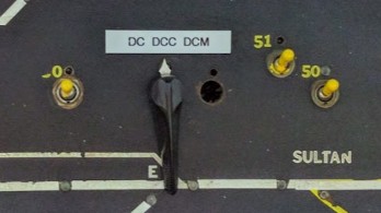
DCM is short for “DCMaster”, an obsolete vendor-specific technology from Broadway Limited to address sound engines running on DC analog track.
From what was gathered, there was a rationale to keep the layout operating in both DC and DCC modes. First current members probably had a lot of DC engines which were not DCC compatible (it’s expensive and not trivial to convert a DC engine to DCC). There also seems that there was a split in the group between those in favor or against this evolution. Finally the “Junior Engineering Day” event (in which the club invites all museum visitors to run the trains) was only set up to work in DC as the engines used were not compatible with DCC.
From my point of view, the conversion was cleverly done and really well executed. Yet it does result in panels which end up more complicated than needed. The procedure to change the layout between DC and DCC mode was quite complex and error prone, involving changing toggles on both control tower panels and switching a number of power supplies. The procedure was not written down anywhere and only a couple members really knew what to do.
What’s behind these ‘DC / DCC / DCM” selectors… 3 relays and a lot of complicated power routing,
all that for a feature we never use and which is not even connected anymore.
Several key people wished the existing control panels stayed as-is, because of the nostalgia and historical significance. The problem is that this complexity has a cost. There has been a lot of iterative work on this layout over its fifty years of existence. There is a lot of obsolete wiring under the layout, it’s extremely hard to figure out if a given thing is actually used or not. The panels have the same issue. They have seen multiple iterations, with empty holes that used to host toggles doing who knows what. There are a lot of lights and wires for a former block occupancy system that is nowhere to be found. There have been additions hastily crammed in a corner in order to not change the rest of the panels. The list goes on.
4.2- Existing Wiring
Note: I’ll shortly describe the existing wiring of this layout here. This is not exhaustive. I also want to emphasize upfront that this is absolutely not a good model to follow for DCC wiring. I expand on the wiring in section 6- DCC Bus Wiring below.
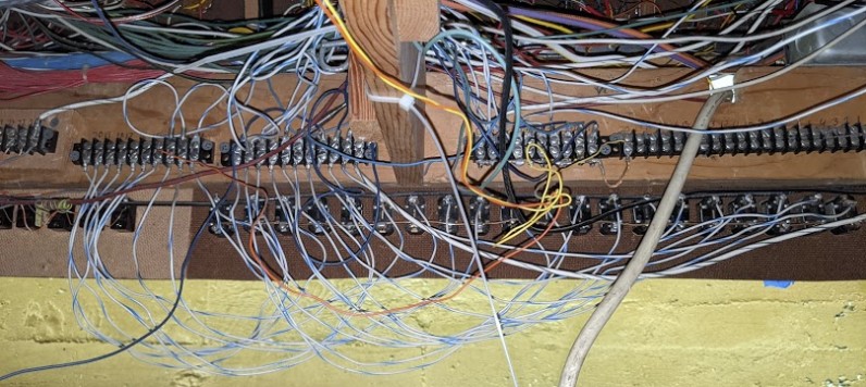
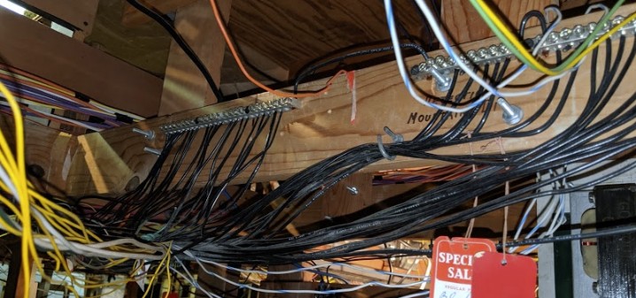
There is a lot of wiring under that layout. A lot of it. A lot more than one would imagine.
Some of that wiring obviously dates from the original DC design. The current wiring is a mixed bag. In some places it’s very clean and logical, on others it’s frankly just a big mess, with some remnants of wiring that goes unused. Then on top of that was layered all the DCC work and a bunch of more modern relay work, which although clean and logical adds one more layer of complexity.
Here’s an example of wiring under the layout. The next picture shows the block power leads out of the Mountain Panel. A bundle of red wires come from the panels, and another bundle of red wires goes to power the blocks on the mountain:
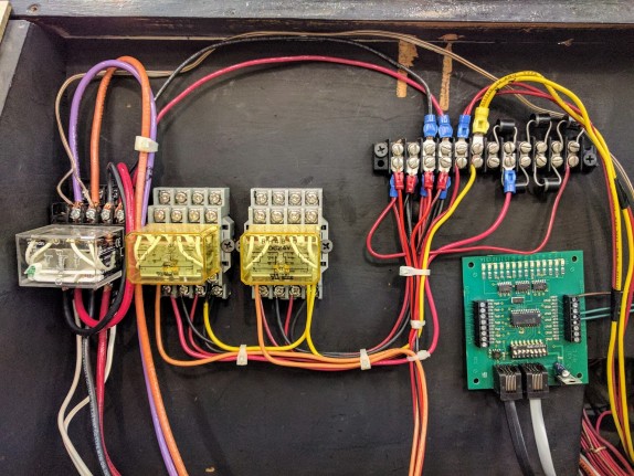
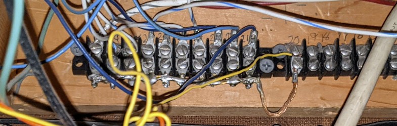
Here’s the back of the interconnection board. The resistors are bias resistors from Twin T detectors (see note below):
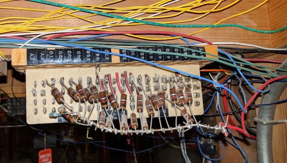
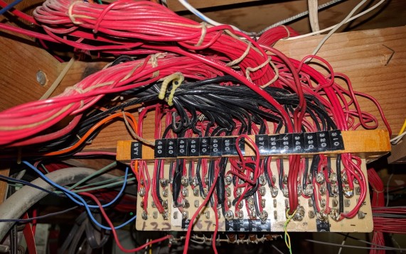
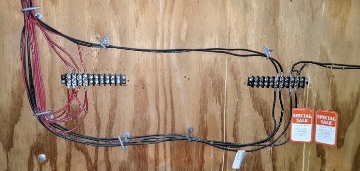
Speaking of bundles of wires:
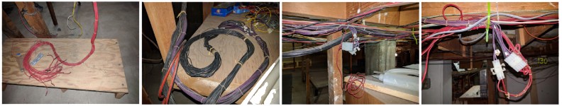
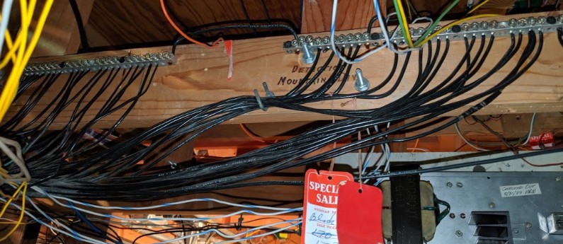
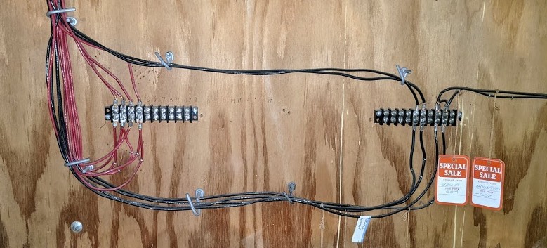
On the left above is one of these bundles of red wires from that interconnection board above. It just wraps around and has been cut. The whole interconnect board is such a mess that I’m afraid of even trying to remove these obviously unused wires. Next picture shows the bundles of black wires. These were traced going all the way to the back room of the layout -- we’re talking 40-50 feet away, then connect to a bundle of purple wires which go back in the reverse direction -- along the bundle of black wires for a while, except from time to time they split off and end up connecting to some red wires (but not the ones from above). As explained to me by Mr. Perry, all these things -- the bias resistors and the extra bundles of wires -- are remnants of an old system of block detectors when the layout was wired exclusively in DC and no longer serve any purpose with the layout in DCC.
4.3- Plans
Two sets of plans were found, ones that look like “historical” original ones, and a later set from Mr. Perry from 2000/2007.
I have no idea how relevant the original plans/schematics are with regards to the current state of the layout. These were scanned (TBD: and should be posted in some fashion here after clean up).
The ones from Mr. Perry seemed quite relevant, and they describe a bunch of relays doing active power routing around some of the complex track intersections and interexchange tracks back from 2000~2009 when the layout was still running in DC. All the equipment is still intact on the layout. Mr. Perry’s DXF schematics were reconstructed as SVG and PDF here:
Randall Schemas - SD+DOW - 2018-11-11.pdf
(TBD add Branchline interchange schema as PDF… currently shown in 15.2- Branchline Main Panel)
4.4- East-West, Running Direction, Polarity, and Common-Rail
East-West
- On the Mountain Panel, East-West to left-to-right:
- [Left] East < Summit < Sonora < Stockton < West [Right]
- On the Valley Panel, East-West to left-to-right:
- [Left] East < Stockton Yard < Timber Creek < Sultan [Right]
- When looking at the Stockton Station from the public area: East is Left, West is Right.
- However when reading the Stockton Passenger Station schematics from Mr Perry:
- Approach West is to the left, and Approach East is to the right.
- The passenger tracks are split into West | Center | East from left-to-right.
- This is reversed to every other panel on the layout.
There are actually two conventions on the layout:
- Both original Mountain Panels and Valley Panels have labels “ ⇐ East | West ⇒ “.
- The schematics for the Stockton Passenger station, redone in 2000, use the reverse direction.
I am going to adhere to the original direction as it makes more sense, the one on the two main older panels. For example running from the town of Stockton, CA towards Sonora, CA is a West-to-East travel direction. This logically puts the Summit / Cajon Pass and the Tehachapi Loop to the East of Stockton to match their geographical counterparts.
The “East / West” and “E / W” signs are clearly visible at the top of the Mountain and Valley panels.
Running Direction
Allegedly, the apocryphal story is that the layout was designed to run in a East-to-West (left-to-right, counterclockwise) direction but in the 2000s the main running direction changed from West-to-East (clockwise) because it provides smaller gradient slopes. And indeed the grade on the Devil’s Gate Loup / Tehachapi Loop is fairly steep and the current running direction makes that a downgrade.
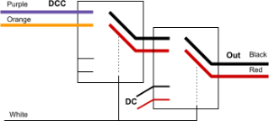
This would explain the electrical wiring design with the common rail is the left one in a left-to-right running direction, and that logically puts the “red” rail on the right side, which is a common practice (“Red is Right Rail” being a mnemonic that I’m used to, as used in DCC decoders wiring). See schema below.
Common-Rail
This is a common-rail layout design with power districts.
One would expect the power district boundaries to be double gapped and the block boundaries to be single gapped.
In the original direction of running from East to West (Left to Right in front of Stockton Station):
- Red is Right Rail -- the outside rail (front-most to the public) is the “red” rail.
- Common is Left Rail -- the inside rail (far-most from the public) is the “common” rail.
In the current direction of running from West to East (Right to Left in front of Stockton Station):
- Red is Left Rail -- The outside rail (front-most to the public) is the “red” rail.
- Common is Right Rail -- The inside rail (far-most from the public) is the “common” rail.
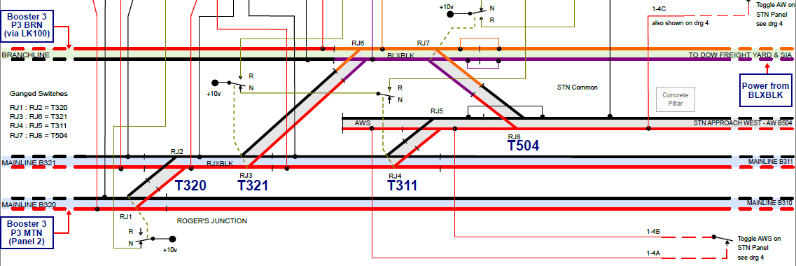
The branchline should match the polarity of the mainline at Angels Camp and the inversion should happen just east of RJ6 (the Branchline/DFS/SIA side of T321). The latter is not necessarily the case due to the way the LK100 is hooked on the branchline power bus.
Track polarity where Branchline meets Mainline at Rodgers Junction:
⇐ East - West ⇒
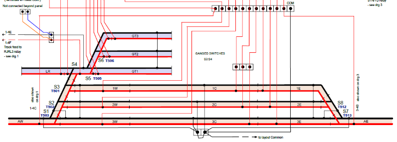
Track polarity for Stockton Passenger Station (please note that this diagram uses the reversed West-East notation specific to the Passenger Station schematics):
⇐ East - West ⇒
Track polarity at the Sonora-Branchline junction [*]:
⇐ East - West ⇒

[*] On the Sonora-Branchline schematic, it is important to note that the track polarity is fixed for the mainline, however that is not currently the case for the Branchline as its entire power district is connected via an LK100 auto-reverser. See 15.1- Reverse Loop for details. I will accept the above schematic as the desired polarity.
(See 4.3- Plans for links to higher quality PDF versions of these schematics).
5- Power Supplies
Under the layout are located many power supplies. Some have proven to be obsolete and not used anymore, and a few are critical. There is no obvious record of which so this section will try to explain what matters.
5.1- Older Power Supplies
In several parts of the layout are located large power supplies attached to the benchwork's support beams. These are totally unconnected. They are part of the original DC throttle equipment dating from the 60s. They are custom made and the schematics are available in the paper archives electrical cabinet. These are permanently mounted to the layout beams. At this point they are of purely historical interest as they show excellent craftsmanship. I left most of them in place, unconnected, and removed a few where space was needed for other equipment.
A typical “DC throttle” power supply. One per panel on the layout.
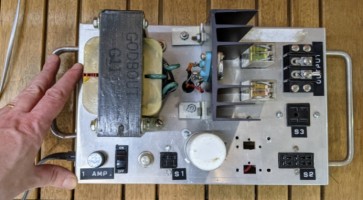
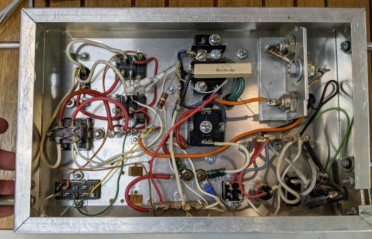
An example of these DC power supplies in situ, here the Stockton Yard panel.
Note the current-limiting light bulb at the top, as well as the DC-DCC relay on the left (with the purple/orange DCC power).
There were several modern MRC power supplies under the layout -- one under each tower and yard, which were connected to the remaining DC throttles. They have all been removed.
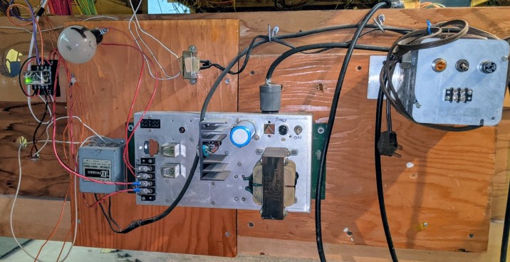
5.2- Building Illumination / Lights Power Supplies
Building Illumination
Many of the buildings on the layout have or used to have illumination.
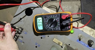
All the building illumination is powered by a fairly old power supply located under the Valley Panel. It is actually used and delivers 9.30 V DC to the building lights.
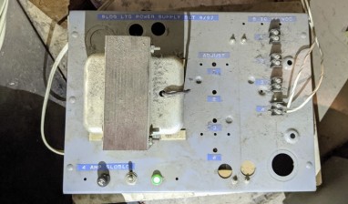
That power supply is quite massive. It measures about 15 in x 25 in. Writings on it:
- Top right: “BLDG LTG POWER SUPPLY BLT 9/97”.
- Top left (by the terminals): “8 TO 14 VDC”
- Middle: “ADJUST”, with labels 1, 2, 3, 4.
- Bottom: “4 AMP SLOBLC”.
The fuse for the bulky 1997 power supply is a “5A 250V 313 Slo-Blow in a 31.75 mm (1 1/4") glass cartridge”. Here’s a mouser link for that kind of fuse. There are adequate fuses in a small box inside the Stockton Yard panel.
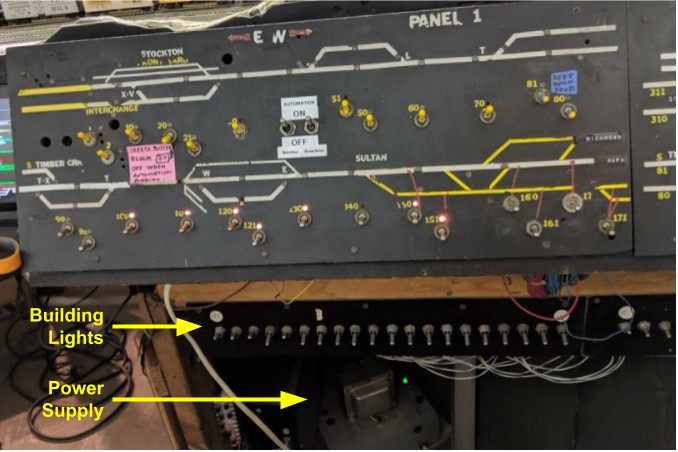
Right below the Valley Panel 1 are a row of unlabelled switches which controls the many building illumination circuits.
All the illumination power buses under the layout use white-with-blue wires pairs.
I had started an effort a few years ago to label a few of these circuits, or at least identify those which still work. Tracing the wires was hard, many went nowhere, and some went to buildings with either missing or burnt-out old-style bulbs (not LED). (update: cannot find these 2015 notes and started again from scratch in 2021).
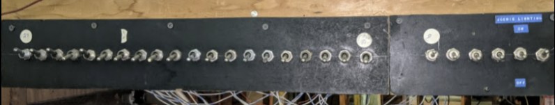
In a typical fashion to this layout, there is no documentation that explains these circuits, and the panel itself has little writing on it. It’s a bit hard to read on the photo, so here are the labels:
- Panel on the left has a blue label “Scenic Lighting”.
- This panel has 9 toggles (picture is not complete above).
- It has two small labels “ON” at the top and “OFF” at the bottom (duh).
- White sticker on the 9th toggle from the left indicates “9”.
- Toggles 4, 5, and 9 are up.
- Panel of the right has 20 toggles.
- White sticker on the left indicates “10” and white sticker on the right most toggle indicates “29”.
- White sticker on the 7th toggle from the right indicates “RH” (I’d guess round house).
- Toggles 25, 28, 27, and 29 are up.
A nice effort would be to re-number these toggles and create a map of where they go on the layout and what works, what is missing. As far as I can remember, two of these toggles control the lamp post by Sonora and the illuminated car at Smith Flat on the Branchline. There’s also a working light in the McDonalds in Fairfield. A few other buildings in Fairfield and Stockton have wires which have been disconnected. Same for the roundhouse.
2021 Update
We spend some time understanding which toggles do produce any kind of lighting today. We could only find these below illuminating anything on the layout:

From left to right:
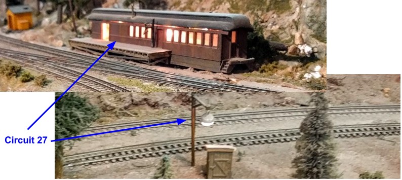
- 27 = Branchline, Sonora Street Light (by the branchline) and the illuminated car on the Branchline at Smith Flat.
- 25 = Mc Donald’s building.
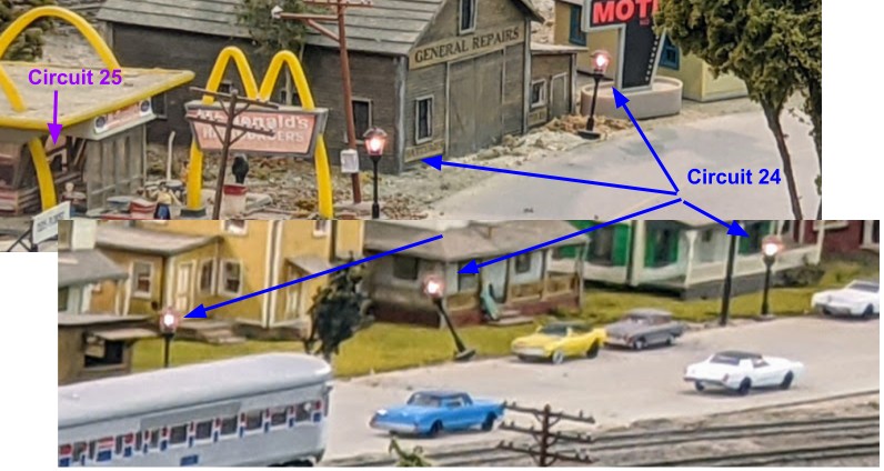
- 24 = Fairfield street lighting (along the street with cars) + the Bekins yellow building.
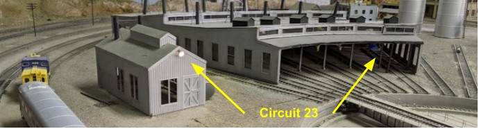
- 23 = Labeled “R H”, powers a circuit in the Roundhouse (disconnected) + a shed nearby.
None of the other circuits seem to do anything. Either they are not used, or they go to places which are not connected, or dead lightbulbs. A bit more of this below; the bottom line a lot of crawling under the layout is involved to figure stuff out.
What we could see on the layout:
Circuit 23, “RH” (hard to see but there’s a wire with some blue tape in the roundhouse):
Circuit 24, Fairfield has many illuminated street lights, and Circuit 25 for Mc Donald’s interior:
Circuit 27, on the Branchline:
Representing these on a map of the layout:
As far as power level goes, the power supply:
- Delivers 15 V when all circuits are off.
- Delivers 10.3 V when the Branchline (27) is turned on.
- Delivers 9.3 V when the McDonalds (25) is turned on.
- Didn’t try with the Fairfield + RH on.
The branchline circuit seems to generate quite a significant power drop given the two paltry lights it powers.
It’s not a good sign to have such a voltage drop. The amps delivered were not measured. The guess is some of these use too much current and the power supply just can’t keep up. We may have to change it if we’re going to power more circuits with it.
Now under the layout, we get to see an interesting story. First, on the other side of the row of toggles, we find this:
It’s a bit hard to see in that picture but there are a few interesting facts:
- Front toggles are numbered 1-to-29 from right-to-left (with only 3 number stickers visible, 9, 10, and 29).
- Terminal blocks on the back are fully numbered, yeah! Oh but wait, they are also numbered 1-to-29 also from right-to-left… See the problem here? Because they are on the other side of that panel, that means they are numbered in the wrong direction. Essentially front panel toggle #29 connect to terminal block #1, and front panel toggle #1 connects to terminal block #29. This will make any engineering discussion quite interesting.
- Even without zooming on that picture above, it’s clear a lot of these circuits are not used.
- Out of the 29 circuits, there are 10 wires leaving the panel towards Fairfield, and 3 wires leaving the panel towards the Roundhouse.
- All the wires have the same color… including the ground ones. Mostly. Yes, lovely.
Next to that terminal block, the perpendicular support has this labeled terminal block:

The white-with-blue wires are the building light circuits. They just pass through. The green wires are the ones going to the terminal with some labels about blocks. Not quite sure which bus that is, as green wires like this are typically used for turnouts in pairs with white wires, and red wires to block power; yet the labels are more indicative of block power. Another mystery for another time. In any case, this labelled terminal block is not relevant to the building lighting.
Anyhow, looking at the details of the terminal blocks, there’s a large 20-position on the right that is unused. Then it’s followed by a 10-position block that seems to be mostly all for common wires judging by how the bottom terminals are all bridged together:
The only circuits that are wired are on the terminal blocks on the left side:
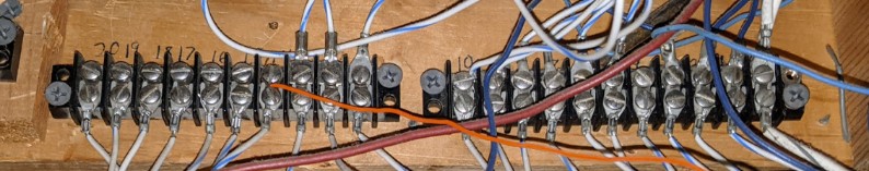
We need to keep in mind that the numbers are inverted with regards to the toggle panel. On the very right side, the big white-with-black wire is likely a ground. Then the one next to it goes to panel toggle #29. From this, it looks like we only have 12 outgoing circuits. That more or less matches the bundles of wires we see going out towards Fairfield (about 10) and towards the Roundhouse (about 3, including ground).
One of these wires from the 10-ish bundle going towards Fairfield seems to loop back under the Stockton Station. However it’s not clear where and if it is used. The Stockton Station has its own lighting circuit which is done using a completely redundant and independent old Bachman DC power pack, with nothing happening when we tried to power it on.
One realization is that these were powering incandescent bulbs, likely the 12 V kind. As long as the original installer could identify two wires per circuit, they did not really need to know which was ground as the polarity does not matter. It’s going to matter when we power lights via a DC step-down converter or a LED circuit though.
Neon Signs
Under the Mountain panel, there are two small power packs. One powers the motel neon sign in the Fairfield town and appears dead. Another one used to power the grade crossing signal at block 120 before the signal and its electronics were removed by a former member with little consideration.
Under the roundhouse, there are 3 small power packs. They power the hotel sign in the town, the theater sign, and the building on fire next to it.
Grade Crossing
2021 Update: The grade crossing has been reinstalled from scratch in 2020-12. It uses a 9 V AC power supply located next to the control module, under the Mountain Panel. See details in section 10.4- Fairfield Grade Crossing.
5.3- Critical Power Supplies
Right behind the DCC Command Station are located 3 critical power supplies:
- A small regulated variable voltage power supply (with 2 knobs and 2 analog meters) is dedicated to the slow-motion turnouts. It's labeled with a "11 V MAX" label.
- Next to it, a similar looking regulated variable voltage power supply was added for the new DCC-controlled turnouts.
- On the other side of the DCC Power Pro is a large gray power supply which is now called the “Auxiliary Power Supply”. It has 3 outputs which provide:
- 24 V DC for the DC / DCC relays.
- 12 V AC for an accessory bus going under the layout, powering various little things (example: tortoise from the branchline, ac-dc converter for the Sonora signal bridge, etc.)
- 6 V AC for … definitely some lights but what else?
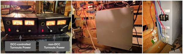
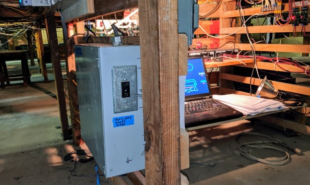
Update: the Auxiliary Power Supply has been moved to the fascia, next to the automation computer, to make it more accessible when it trips:
5.4- DCC Power
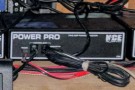
The layout uses an NCE Power Pro and three NCE 5-amps boosters which are then split in 10 power districts.
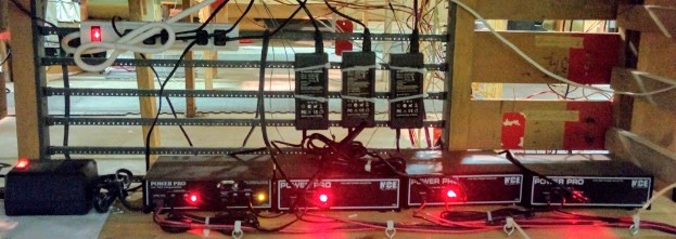
The NCE Power Pro (left) and 3 boosters
Each power district has its own NCE EB1 electronic circuit-breaker for protection against shorts.
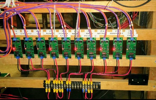
The circuit-breakers for the 10 DCC power districts
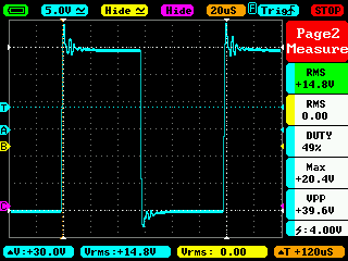
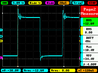
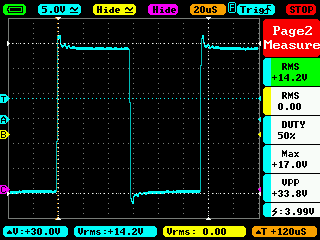
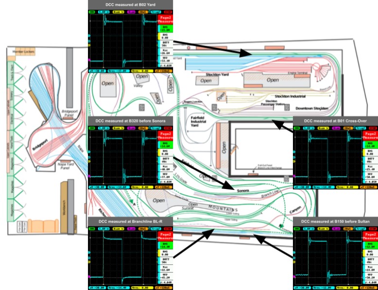
Map of DCC boosters to power districts to blocks (see warning below about voltages indicated):
Booster |
Usage (number of engines [1]) |
Level / noise [2] |
Booster 1 (NCE Command Station) |
P1 V1 (Valley1) … 1 P1 STKYD … 2-4 Valley 1 blocks B70 to B01. |
|
Booster 2 |
P2 V2 (Valley2) … 1 P2 NAPA … 0 P2 TOWN LODI … 0 P2 FAIRFIELD … 1 Valley 2 blocks B170 to B80. |
|
Booster 3 |
P3 MTN-1 … 1 P3 BRN RCH-2 … 1 MTN-1 blocks B390 to B462. |
|
Booster 4 |
P4 MTN-2 … 1 P4 BRPORT … 0 P4 SIA RND … 0 P4 STK STN … 1 MTN-2 blocks B310 to B380. |

Note 1:
- The middle column indicates the name of the power district supported by each booster. Each power district has its own circuit breaker. The “number of engine” is a crude estimation of the load of that district in number of trains typically using that district either during a Saturday ops or a weekday automation. Saturday trains typically have more than one engine.
- Projected extra power districts: Fairfield Industrial on Booster 2, and Stockton Passenger Station on Booster 4.
Note 2:
- The waveform measurements were done without any load (a.k.a. engines) running on the track.
- Warning: the RMS indicated on these voltage measurements is not accurate. You can find an explanation of why the RMS is wrong on this DCC Wiki page. However the RMS values give a good relative indication and most importantly displays the ripples in the waveform.
Note 3:
- Mountain Panel 2 (left side) is P4; Mountain Panel 1 (right side) is P3.
- Valley Panel 1 (left side) is P1; Valley Panel 2 (right side) is P2.
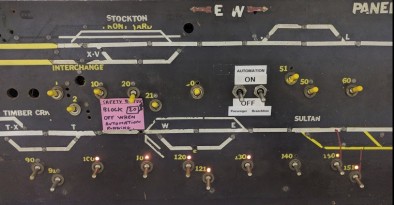
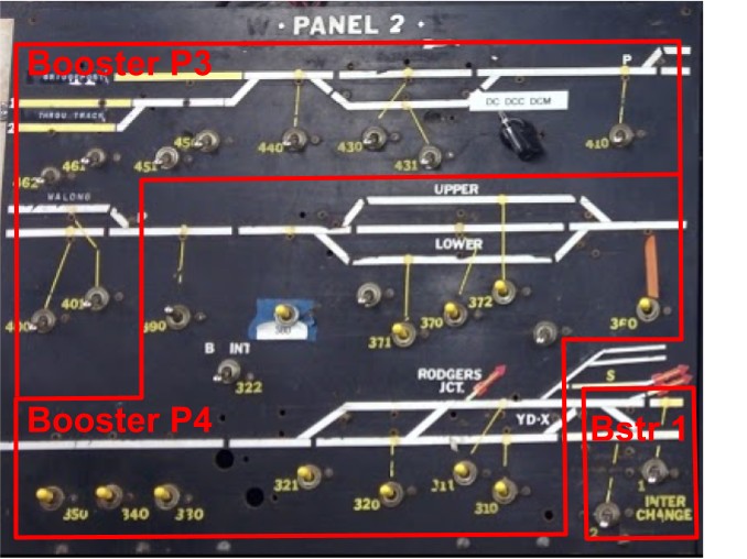
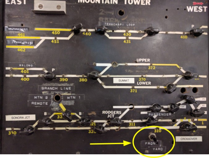
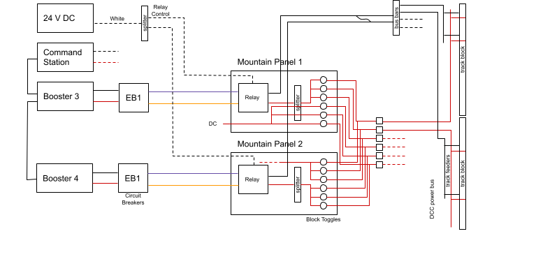
Both control towers (Mountain and Valley) are powered by two boosters each. The block toggles are used to select one booster on one panel for a set of blocks and the other booster on for the rest of the panel. Here’s the split for the Mountain panel, followed by a detailed explanation below:
The DCC conversion made use of the block system and kept it intact. Since each block has two possible power sources, the DCC actually acts as one of the power sources. For example on the Mountain tower, there are Panel 1 and Panel 2 for block control, half of the block toggles on one panel toggle it to DCC whereas the other half is located on the other panel.
These DCC toggles are denoted by a yellow handle. The example above is the Mountain Panel #2. There are two such panels, identical, except:
- On Mountain Panel #2:
- Toggles for blocks 310 through 371 are up (on). That panel is connected to booster 3. The toggles have been painted yellow.
- Toggles for blocks 400 through 462 are down (off). This means these blocks are not powered by booster 3.
- On Mountain Panel #1, the situation is reversed:
- Toggles for blocks 310 through 371 are down (off). This means these blocks are not powered by booster 4.
- Toggles for blocks 400 through 462 are up (on). That panel is connected to booster 4. The toggles have been painted yellow.
- The end result is that:
- All blocks 310-371 are powered by booster 3 via Panel #2.
- All blocks 400-462 are powered by booster 4 via Panel #1.
Technically each panel is powered by a “power district” (e.g. one of the EB1 circuit breakers). These are in turn powered by boosters 3 and 4. The whole point of this scheme is obviously to power the long mainline using multiple boosters.
Since each block has two power supplies in parallel (booster 3 & 4 via panel 1 & 2), when operating it is important that one block toggle be up whilst the corresponding block toggle on the other panel be down, otherwise it does short two power districts / boosters together, which is not good. I’ll detail below how this is wired behind the panel.
The rule when operating in DCC, as is the case here, is that all "yellow" DCC block toggles must be up and all the silver DC ones must be down. There is no written indication on the panels that they work that way. It’s fairly error prone.
To finish here’s a quick survey of the DCC signal measured at different points on the track:
5.5- Room Outlets / AC Power
The room breaker panel is located behind the Pullman exhibit, on the right side when entering the room. At this location we also have the main “North & South” power toggles to turn on power to the layout.
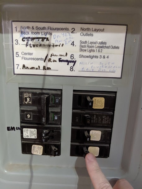
The circuit breaker has an inscription on the cover as having been updated in 1995. Although there are labels for each circuit, they have been further annotated, and their veracity has not been verified. There is also a very prominent “240 V” warning label on it. This breaker is actually a sub-breaker, which power comes from a larger breaker in the heater room. The train room breaker labels read as such (caveat emperor):
- 1 = North & South Flourescents (sic). Back room Lights.
- 2 = North Layout Outlets.
- 3 = Center Fluorescents (crossed). Dryer Animal Room.
- 4 = South Layout Outlets.
Back Room Unswitched Outlets.
Show Lights 1 & 2. - 5 = Center Flourescents (sic) / Animal Room Emergency.
- 6 = Show Lights 3 & 4.
- 7 = Animal Room.
- 8 = North & South fluorescents. Back Room LIC (sic).
The only circuit that has been verified is that #4 does toggle the one backroom unswitched outlet that we need for the computer equipment. The label indicates “Outlets” plural, when only a single outlet was found on this circuit. There might be others located behind cabinets that we cannot easily move.
What are the North & South Circuits?
The room has two rows of concrete pillars: the ones on the left side of the room (by the kids train exhibit, mountain side of the layout) are on the “South” circuit, and the ones on the right side of the room (by the Valley panel) are on the “North” circuit.
One of the outlets of the back room is on a different circuit that is not toggled with the rest of the layout power.
Crude schema of power in the back room (to be cleaned up later):

Details:
- The workbench is on the North circuit.
- The two outlets at waist level on the concrete walls of the backroom are on the South circuit.
- Only the low-to-the-ground outlet on the mountain side of the back room is on the “back room permanent” circuit.
6- DCC Bus Wiring
Pairs with one orange cable, one purple cable, and one dual white cable: the orange/purple are fairly large AWG, maybe 12 or 14, stranded. The white one is regular power cord cable.
The orange/purple cables are the output of the DCC circuit breakers and they bring power to each DCC power district. The white cables are connected to the 24 V DC panel and trigger the DC / DCC relays once the DCC main switch is turned on.
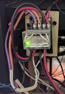
6.1- DCC / DC Power Relays
This can be seen next to the DCC Command Station where the circuit-breakers are located:

Under each tower panel (one per block panel), there's a relay with the other side of the orange/purple cable. The relay acts as a dual 1PDT that toggles between the DCC or the DC input: This double-relay scheme means that some DCC-only equipment can be powered only when the DCC is up (see 11- Branchline below for an example). The output are the two large black and red wires. |
How this is used depends on the control panels. There are different cases for yard panels vs the mainline control towers.
6.2- Block Power for Yard Panels
The yard districts are each powered via their respective yard panels, which typically feature both block power toggles and turnout toggles.
For most yards, there is first one 3-position selector to select the power feeding the whole yard, and then each block has a simple on/off power toggle. Typically the 3 power selections depend on where the yard interconnects with the mainline. We need to remember this was designed for DC usage, which track voltage dictates train speed. In this mode of usage, it is typical to power either the full yard or at least an interconnection track with the mainline, bring the train in or out from the mainline, and then switch the yard to its own independent yard power pack.
I’ll give two examples as these are the cases I had to look into to solve issues.
Richmond Yard has the choices of Throttle 1, Throttle 2, or Yard. The “throttle 1” and “throttle 2” cases are connected to the mainline’s DC throttles. Once a train is in or out of the yard, it can be changed to its own yard DC power pack.
DCC conversion of Richmond Yard: Throttle 1 is connected to the DCC bus, on its own booster / circuit breaker. Throttle 2 is not connected to anything. The DC yard power pack is still present but not powered and not used.
Down the line, it would be useful to clean that up by replacing this 3-position toggle with a simple on/off toggle, only connected to the DCC bus. This would prevent operator errors not understanding why the whole yard loses power.
Stockton Yard also has two unrelated power selectors.
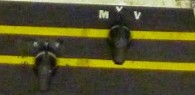
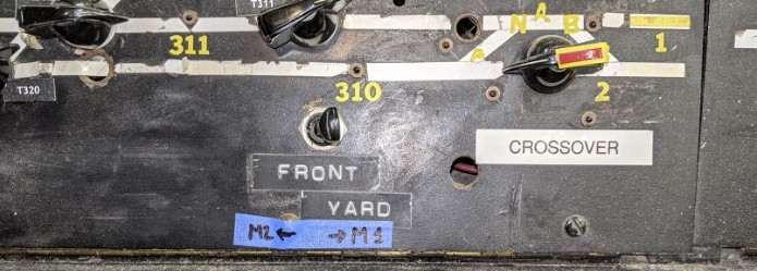
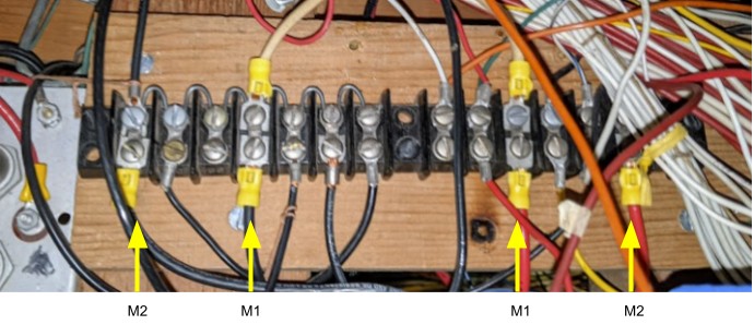
- The two interconnection tracks (in yellow) going to/from the yard to the mainline have a selector with three choices: M, Y, V. “M” is the power from the one of the Mountain Panels (as selected by the Front Yard toggle there which selects Panel 1 or 2), “Y” is the yard’s dedicated DC power pack, and “V” is the power from the Valley Panel (as selected by the Front Yard toggle there which selects Panel 1 or 2),. This dictates what the Stockton Yard panel receives when set on the V selector.
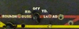
- The interconnection track (in red) going to/from the Roundhouse Yard has a selector with three choices; Rh, Off, Yd. This allows the track to be powered from the Roundhouse panel, be off, or be powered from the yard throttle.
For the DCC conversion:
- The “Y” side is connected to the yard’s DCC input which comes from Booster P1 with its own circuit breaker. This is the only recommended position in DCC.
- The “M” side is connected to the output of the “Front Yard” toggle on the Mountain Tower. This is not recommended in DCC.
- The “V” side is connected to the output of the “Front Yard” toggle on the Valley Tower. This in turn connects to the Valley Panel 1 (Booster 1) or Valley Panel 2 (Booster 2), which each have their own circuit breakers. This is not recommended in DCC.
In DCC, it’s important for the “M,Y,V” selector to be set to Y. It means the interconnection track is protected by the same circuit breaker as the rest of the yard. For a while it was incorrectly set to “V”, and although everything seemed to be working fine, it meant that any short in the yard would also short the mainline, thus producing hard to understand issues.
Down the line, it would be useful to clean that up by replacing these 3-position toggles with simple on/off toggles, only connected to the yard’s DCC bus. This would prevent operator errors toggling these by mistake and not understanding their consequences.
6.3- Front Yard toggles on Mountain and Valley Panel
The interchange tracks in the Stockton Yard panel are powered via a 3-position toggle:

When the Stockton Yard power selector is on “V”, power is selected from either Valley 1 or Valley 2 using the “Front Yard” toggle on the Valley panel. It’s a 3-position toggle, and the middle one is unused, leaving the wire unconnected.

When the Stockton Yard power selector is on “M”, power is selected from either Mountain 1 or Mountain 2 using the “Front Yard” toggle on the Mountain panel. It’s a 3-position toggle, and the middle one is unused, leaving the wire unconnected.
A label was added to make it easier to remember which sides selects power from which panel:
When the Stockton Yard power selector is on “Y”, power used to come from the local DC throttle, which is now connected to the yard’s DCC power district.
6.4- Block Power Selection for Mainline Control Towers
As a recap, each panel receives DCC power directly from a circuit breaker. Under the panel, a relay is used to select DCC vs DC power source.
The relay acts as a dual 1PDT that toggles between the DCC or the DC input:

In the Mountain Panels and the Valley Panels, the DC side was further connected to two additional relays to select between DC and DCM inputs. The DC part could further come from MRC power supplies using radio throttles, or from local wired “knob” DC throttles.
Let me rephrase that to let it sink. That means the power source for each of these panels can come from:
- A local “knob” physical power pack.
- A local DCM power pack.
- A local MRC Radio Control power pack (with its associated walkaround analog radio throttle).
- A DCC booster (via a dedicated DCC circuit breaker).
Furthermore, each individual block can be powered from either the panel 1 or panel 2 of its corresponding tower.
As part of the DCC simplification, we removed the dual relays and the DC/DCM power sources to simplify the panels, and the DC part of the relay is not connected to anything anymore. The main relays were left in place as they can be very handy (I typically simply remove the relay from its socket base to disconnect an entire panel and work on it).
On the output side:
- The black wire goes (indirectly!) to the DCC power bus.
- The red wire is split and then fed to the smaller red wires for each block toggle.
Black Wire Side
For a while I naively assumed the black wire out of the DC / DCC relay was connected directly to the DCC bus going to the track. It turns out that’s not the case. Both the Mountain division (Mountain 1 & 2) as well as the Valley division (Valley 1 & 2) are each wired with all the “common grounds” wired together. These are located under the Valley Tower panels.
Under the Mountain panel, this terminal bridges both Mountain 1 and Mountain 2:
Every single block in the Mountain division has its black rail wire connect to this bus bar, located under Stockton Yard:
Each black wire connects to a specific block in the mountain (which is on the very opposite side of the room), they are all interconnected together with the bus bars, and from there two black wires go back to the Mountain Panels in the middle of the room. As can be seen in the middle, both bus bars are bridged together.
A side effect of this is that it absolutely merges the “common” from boosters P3 and P4.
For the Valley division:
(TBD… get a better picture and add it here).
And finally this merges all the commons together for all the “isolated” yards:
This is also located under Stockton Yard.
An important note: it should thus be assumed that none of the four DCC boosters are actually isolated from each other. A safe assumption is that all their common/black/negative outputs are eventually cross-linked somewhere under the layout.
Red Wire Side
The output of each block toggle connects to an interconnection board under the layout using red wires (see picture above in 4.1- Wiring). For each block, the interconnection board takes two red wires from Panel 1 or Panel 2 of the mountain or valley panel, and outputs one red wire towards the track block. The red wire then joins the black wire and forms the DCC power bus for that block, on which feeders are connected to the track.
To understand how power selection, let’s look at the control panel of the Mountain tower, for example:
There are two panels, “Panel 1” and “Panel 2” which are replicas and have the same track layout with the same block toggles. Earlier I explained how this is used to power half the blocks from one power district and the other half of the blocks from another power district and thus different boosters.
Each block has a number and they are equally present on each panel. However on Panel 1 only half the toggles from the top are connected to DCC whereas on the Panel 2 only the ones from the bottom are connected to the DCC. The output of each block of the same number is connected together via the interconnection board indicated earlier under the layout, thus merging both sides.
This is the wiring behind the scene:
Since there are about two dozen blocks on each panel, each panel powers about a dozen DCC blocks. There is a similar setup for the Valley panels.
Now this requires a little bit of a discussion. The schema above is definitely complex and may seem odd to someone used to modern DCC bus wiring. It does make more sense when one considers this was a pure-DC layout: two independent DC throttles would power Panel 1 vs Panel 2 (thus different voltage for different speeds) and block toggles on the panels would allow a given block to be powered by power supply 1 or 2. The DCC conversion reuses that and instead powers the panels from booster 3 or 4.
Consequently it is crucial that a given block be OFF on one panel and ON on the other one, but not turned ON on both at the same time -- otherwise it literally shorts two boosters together.
I expand more on the issues for DCC wiring in section 6.8- How Not to Wire a DCC Layout below.
6.5- Valley DC Power Selection
The Valley Tower with its power panels 1 & 2 follows a fairly similar scheme to the one described just above for the Mountain Panels.
It does have one extra little twist which is worth noting, with this selector located under the panel to choose between “Knob” and “Radio” for the Valley 1 panel…. (there’s a similar setup on Valley Panel 2).
This deserves some scrutiny and understanding.
To start, on the second image above on the right side we can see the DC / DCC relay (only the base socket, I typically remove the relay itself when I work on the wiring, to ensure electrical isolation). The DC input used to be from the top of the relay socket and has already been removed.
The two large black and red wires at the bottom of the relay socket are the output for the panel. However they do not connect directly to the panel.
Instead the output of the relay is connected to the “Knob / Radio” selector on the Radio side. This in turn is connected to that terminal block seen in the second picture on the left side.
Finally the red and block wires seen on the terminal block are connected to the block panel 1.
The schematic of the power routing can be explained as such:
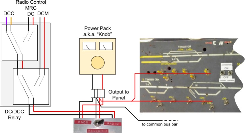
This explains where the “Throttle 1” can be powered from for the Valley Panel 1:
- From the DCC -- in this case the output of the DCC Command Station via an EB1 Circuit Breaker.
- From the MRC Radio Control (analog DC supply).
- From the DCM (analog DC supply).
- The output of this goes to the “Radio” side of the selector knob under the panel.
- The “Knob” side was connected to a custom-made “power pack” (DC supply) with a large knob and two vu-meters.
- The output of this selector goes to the panel -- at least the red wire goes there directly, whereas the black wire goes to the common bus bar that collects all the black wires from each block.
As part of the DCC conversion:
- The MRC analog radio, the DCM analog DC, as well as the “Knob” power pack all have been removed.
- The panel has been connected directly to the DC / DCC relay.
The Valley Panel 2 has exactly the same setup.
6.6- Common Rail
As far as my limited understanding of such things goes (a.k.a. “please correct me if I’m wrong”), then I’d tend to say the layout uses Common Rail wiring and what exactly happens between power districts is mostly clear to me.
As an example, let’s take the Mountain division; please refer to the overview simplified schematic provided in the previous section. The division is covered by 20-30 blocks and two panels (Mountain 1, Mountain 2). Each panel is powered by its own booster via an EB1 circuit breaker. Black and red power buses deliver power to the track. The black wires run (indirectly) from the panel’s DCC black to the DCC bus and the track feeder’s black wires. The red wires are first routed via the panel for the various block toggles -- and for each block, power for the “red” feeder wire can thus come from the panel 1 (booster 3) or panel 2 (booster 4). However the return black wires are all connected together via an interconnection bus (see picture below).
Question is what happens between panels, for example are all the black return wires from Mountain Panel 1 eventually also connected to the ones from Panel 2, even though power originates from different boosters? The answer to that is definitely yes as shown in 6.2- Block Power for Yard Panels.
But what about between panels from Mountain Tower and Valley Tower, are their commons also connected together? Anecdotal testing indicates that they are indeed connected, although it’s not clear how and where.
Similarly, although each yard can have its independent DC power supply, their common grounds are all interconnected.
Follow up question: since the layout uses common rail, have the boosters been modified to follow the NCE procedure to use them with common rail wiring (link here)? In this case, yes they have -- each booster was opened to double check, and the screw YY to isolate the booster from the ground had been removed. And in this case, should the NCE procedure to ground the case of all the boosters be followed? Yes and no. It’s mostly useless -- the point of that NCE procedure is to isolate the boosters since removing the screw YY isolates the booster’s metal enclosure from the circuit board and to prevent the outputs from being grounded together via the boosters’ metal enclosures -- however that point is rendered moot since the layout effectively grounds all boosters commons together anyway. Still I think it’s good to have the metal enclosures grounded so I added that.
One must realize that the NCE procedure’s goal is to isolate each booster's common wiring. That’s why the screw YY is to be removed. Which conflicts with the design of this layout where all the commons are voluntarily reconnected together after yards and yards of extra useless wiring. We cannot achieve proper booster/district isolation without a very involved rewiring of the entire layout.
Some (all?) district common grounds are interconnected. This is located under Stockton Yard.
All common wires for Mountain 1 and 2. This is located under Stockton Yard.
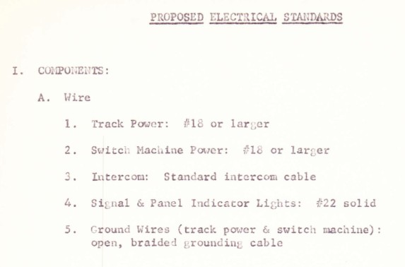
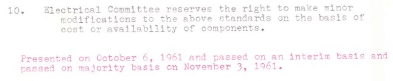
6.7- Electrical Standards
From the 1961 paper archives of the layout:
The following table is based on visual observation of “key” wiring under the layout. The list is not exhaustive.
Gauge |
Color |
Era |
Usage |
12 AWG Stranded |
Black + Red |
DCC |
Boosters to EB1 circuit breakers. |
10 AWG Stranded |
Orange + Purple |
DCC |
DCC EB1 circuit breakers to DC/DCC relays on panels. |
16 AWG Stranded |
White extension-cord pair |
DCC |
Trigger for DC/DCC relays. 24V AC. |
16 AWG Solid |
Red + Yellow |
DCC |
Used in “new” DC power buses. |
16 AWG Stranded |
Speaker Wire |
DCC |
Used on “newly” installed turnout rotary toggles typically to newer Tortoise switch machines. 12V DC. |
16 AWG Stranded |
Green + White |
DC |
Used in old turnout rotary toggles from Mountain/Valley panels. 12V DC. |
~22 AWG |
Communication Wire (Black, Red, Green) |
Automation |
Used for short-distance sensors to NCE AIU01 on Passenger Panel. |
24 AWG Solid |
Green + Green/White twisted |
Automation |
Already twisted. Used for BD20 sensors & connections to NCE AIU01. |
Notes:
- Solid = Not stranded.
- 16 AWG stranded wire is not marked so that’s just a visual estimation; it could be 18 AWG.
- The 10 AWG wire that brings DCC to the Mountain and Valley panels first connects to some terminal under the layout, and from there goes to the panel using unmarked 16 AWG stranded wire.
- “New” means stuff likely dating from the DC/DCC conversion, so after 2010-ish.
- Era: DC < 2010. DCC >= 2010. Automation >= 2016.
My own electrical standards are as follows:
Gauge |
Color |
Usage |
10-12 AWG Stranded |
Black + Red |
DCC Power Bus. |
16-18 AWG Solid or Stranded |
Black + Red (ideal) (as available) |
Low power DC Power Bus. 12V DC or AC. |
16-18 AWG Stranded |
Green + White |
Turnouts Power. 12V DC or AC. |
22-24 AWG Solid, twisted |
Green + Gr/White |
Block detectors, sensors, low power short distance 5V wiring. |
RJ12 6P6C Straight |
Gray |
NCE Cab Bus. |
Note: Polarity is extremely important for all DCC buses on this layout due to the heavy common ground influence. Always assume all blacks are connected together. When there are power block toggles, only the red side is interrupted.
6.8- How Not to Wire a DCC Layout
The current wiring on this layout does not follow modern DCC practice.
As noted above, the current situation is the result of adapting a former DC layout to also support DCC. I think the transformation was cleverly done given the initial medium; however it results in a DCC layout with poor electrical performance.
Let’s look at what one should do to properly wire a club-sized layout in DCC:
- Have a strong & consistent convention defining wiring gauge sizes and connections.
- From its original construction as a DC layout, it’s clear the layout had clear 6.7- Electrical Standards, and these are fairly well followed on the majority of the mainline. The original yards (Stockton and Bridgeport) are also very consistent.
- However that’s not the case with later additions. The Branchline follows different electrical standards for wiring (but it’s fairly consistent); and Lodi itself is extremely inconsistent.
- The wiring between DCC boosters and then panels is consistent, and matches reasonable electrical standards.
- The current DCC practice advocates using twisted pairs for DCC buses over 30 feet (and even below if possible). This avoids crosstalk and reduces unbalanced noise issues in the digital signal. We totally lack this here, and it shows several issues with some specific brands of decoders (e.g. the BLI ones, which are finicky at best).
- That was not a practice needed in DC, and as such is not followed here.
- On the contrary, we have unbalanced black vs red wiring following dramatically different paths, with all wires mixed together with other wiring from the layout such as turnout control or accessories power buses.
- The path taken by the DCC power bus from the DCC boosters to the track can be well over 30 feet. The biggest culprit is probably the Mountain Districts wiring: A random back-of-the-envelope estimation is that going from the DCC boosters / circuit breakers to the Mountain Panel is probably 30 feet of wiring all by itself and is using non-twisted wire. Then the DCC wiring goes through the panel itself (2 relays + 1 block toggle + 1 terminal + 1 interconnect bar) before leaving for another 10-30 feet before reaching the blocks’ feed wires. On top of that, the return path (the “black wire” of the DCC bus) on the Mountain division follows some kind of complicated and unusual path adding about 50-60 feet of wiring (see 4.1- Wiring).
- Power districts and booster isolation.
- This is achieved on a DCC layout by having gaps on both rails between power districts. Only gaps for block detection can be made on a single rail.
- This layout uses the DC “common rail” design (see 6.6- Common Rail). Even when the track has gaps on both sides, the common rails are bridged together at the main panels, and in turns all the common grounds for all panels and power districts are bridged together at a central location under the layout.
- To make matters worse, there are various interconnects between the panels to cross-feed a control panel using the power from another power panel. This can potentially bridge different boosters together.
- We still have some “phantom power” on some blocks. In specific places, even if I turn the block off using the panel toggles, the track is still powered with some kind of DC-offset signal from some other place which I do not manage to trace. That means there are some cross-feed power connections I still do not understand nor control.
7- Mainline Turnouts
Turnouts control represents another interesting topic.
The layout uses 3 kinds of turnouts: twin-coils, Fulgurex and Tortoise. It seems that twin-coils are used in the yards and the original mainline was apparently using Fulgurex turnouts. Later, some of the mainline and yard were changed to more modern Tortoises.
Turnout panels use rotary switches for Tortoise and Fulgurex turnouts (mainline) and push-buttons for the twin-coils (all yards).
The existing turnout panels all use non-momentary rotary toggle switches.
Power is provided by a regulated variable DC power supply located next to the DCC Command Station as indicated above.
Each rotary toggle switch is a 6PDT with only 2 poles used, so it ends up being the typical DPDT wired in a cross-over configuration. Turning the toggle effectively inverts the input polarity.
Input is the DC turnout power (red wire is negative, white wire is positive). Inside the panel, all red wires are connected together using a terminal block where all terminals are connected together with a bare wire.
Output of each DPDT is 2 wires, white and green. The whites ones travel directly to the corresponding turnout. The green ones are connected to another 1-to-1 terminal block inside the panel.
Schematics of the original wiring:
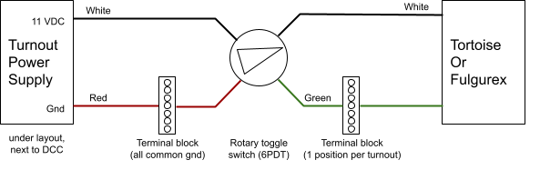
Each panel has about 20 turnouts toggles. In that case, the white input wire is a common wire. The red terminal blocks splits in the single red input for all the turnouts. On the output side there are as many white/green pairs as there are rotary toggles.
It’s important to note that these rotary toggles are permanent contacts. This works well with Tortoise or Fulgurex.
The yards use momentary contact push-buttons connected to yard ladder matrices and twin-coil turnouts.
A few miscellaneous notes:
- “Old” twin-coils (as still found under Fairfield or in the yards) are powered by a 12 V AC bus. They are not DC-compatible. Regarding those from Fairfield, only half are working properly; the other half either have one coil not working or mechanical issues or both. Yard ladders for Stockton and Napa use twin-coils and are working properly.
- There’s a box of 10-20 of these in the electrical cabinet which have been removed from the layout. I was told the reason is they were partially dead and replaced by Tortoises.
- The Branchline has Tortoises setup in places such as the interchange tracks. These are powered via the 12 V AC bus using 2 diodes (see below for details).
- A handful of turnouts on the mainline are not operative. They are either old twin-coils disconnected, or Fulgurex that don’t work. Some are not connected or lack a rod/wire. Examples are Walong (block 400) and the mainline in/out of Fairfield.
Failure modes / known issues:
- Twin-coils:
- Symptom: A turnout that easily throws in one direction yet fails to throw in the other direction.
- Reason: Often one of the two coils seems to have failed.
- Solution: Replace whole assembly or do not use.
- Twin-coils:
- All the layout twin-coils are of the 12 V AC type.
- Coils can be either DC or AC. The ones used require an AC voltage.
- They will not work if powered by the Turnout Power Supply used for Tortoise / Fulgurex.
- Fulgurex:
- Symptom: A Fulgurex that seems to slow throw in one direction yet too weak/slow to throw at all in the other direction. Measuring the voltage will show they receive less than their required 10 V.
- They require a fairly strong current, nominally 200 mA at 10-12 V.
- They cannot be powered directly either by a Digitrax DS64 or an NCE Switch-8 -- Note: I did have some success with the DS64 but it’s really hit-and-miss and as such is not recommended as it exceeds the amps output of the DS64. In this case, the 12 V output from the DS64 collapses to 3~5 V, which is not enough.
- Fulgurex / Twin-coil:
- Symptom: Trains stutter when crossing the frog.
- Reason: The frog is powered via contacts on the point motor. Oxidation of the exposed contacts creates some resistance which reduces power delivered to the engines. Measuring with an ohmmeter will typically show a non-negligible resistance (e.g. 100 Ω).
- Solution: Either swap the point motor, or at least try to clean the exposed contacts using some CRC 2-26.
- Twin-coil:
- On some of the twin-coils, the contacts have obviously lost their springiness and no longer make a good contact.
- Solution: Swap the whole unit. Trying to bend the contacts has never proved successful.
- Fulgurex:
- In one instance, the DPDT contact spring had gone AWOL.
- Solution: Replace the spring in place from another Fulgurex. It is possible, albeit tedious. Or swap the whole unit.
8- Stockton Station & Stockton Yard
8.1- Stockton Station
The Stockton Station is certainly the most visible feature of the layout when visitors walk in the room and approach the middle of the room.
Track plan:
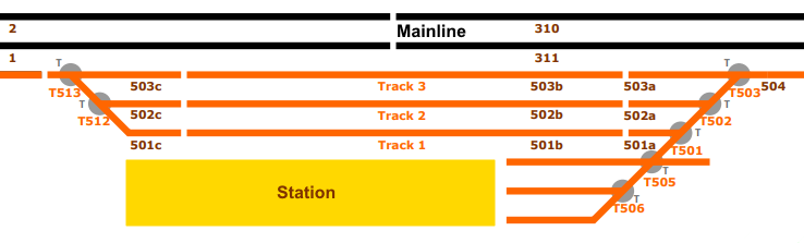
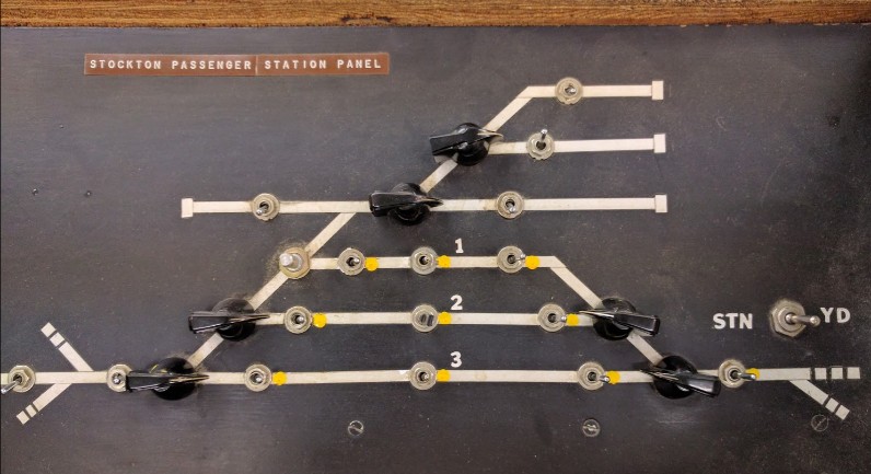
Control panel:
DC operation, as explained by Mr. Perry:
- The station is connected to the East (right side) to the mainline, or the Stockton yard, or the roundhouse lead. This is the Approach East block.
- The station is connected to the West (left side) to the mainline at block B311 or the branchline via T504. This is the Approach West block.
- Tracks 1, 2, and 3 for the station are composed of 3 segments (West, Central, and East), each with a power selector: left for West approach, middle for off, and right for East approach.
- Power for West comes from:
- Block B321 if T311 is thrown to connect the station to the mainline track #2.
- Block B320 if T311 and B320 are thrown to connect the station to the mainline track #1.
- Branchline if T504 is thrown to connect the station to the branchline.
- Otherwise from a local West Power Controller (no such power supply was installed though).
- Power for East comes from:
- Block B10 when T04 is thrown, connecting the station to mainline track #1 in front of the yard.
- Block B21 when T04 and T05 are thrown, connecting the station to mainline track #2 in front of the yard.
- The Roundhouse Cab power when T604 is thrown, connecting the station to the Roundhouse Lead.
- Or the Stockton Yard power when neither of these turnouts are thrown and the STN/YD switch is set to YD.
- Or to a local East Power Controller when the STN/YD switch is set to STN, or T03 was thrown. No such power supply was installed on the layout, though, so in this case the station would have no power.
- The 3 spurs at the top have their own power through the West Power Controller.
(Important Warning: all the Passenger Station schematics by Mr. Perry uses a reversed West-East notation, which contradicts the one used by the rest of the layout; I kept the description above intact because the names are on the layout wiring, but I want to make it clear that they are the reverse of my convention of East-West meaning Left-Right meaning a clockwise run; on my schematics I use block numbers instead of names to avoid this kind of confusion).
When the layout was powered in DCC, DCC was injected on the “right” side (East approach) and would indirectly come from either the mainline, the roundhouse or the stockton yard (by default). That’s the reason why each block power selector has a “yellow dot” on the right, to indicate this was the default setup. The inconvenience of this scheme is that the station would lose power when T03 was thrown, or the STN/YD switch was thrown to STN side.
TBD 2020: Document changes done to power relay on T03.
8.2- Stockton Yard
The Stockton Yard is actually composed of two different yards: a freight yard and a passenger yard. There’s an engine facility as well as a roundhouse. Note: An overview of both yards as well as a track plan were provided in section 1- Layout Design and won’t be repeated here; instead we’ll focus on some details.
One particularity of the yard is that it connects with the mainline via a double slip switch and a crossover which are controlled from the two different panels:
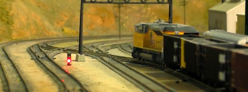
The schematic for the power routing is quite amazing (full link here, drawing page #3):
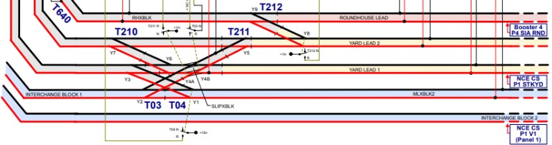
The yard interconnection tracks turnouts are controlled from the Stockton Yard panel, whereas the turnouts on the mainline (in blue on the schema above) are controlled on the Valley Tower panel.
The round house:
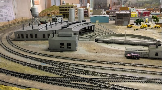
Passenger yard and engine facility:

The freight yard:
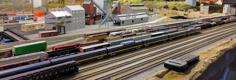
9- Stockton Industrial Area & Dow Freight Sidings
The SIA (Stockton Industrial Area) & DFS (Dow Freight Sidings) are located right behind the Stockton Station.
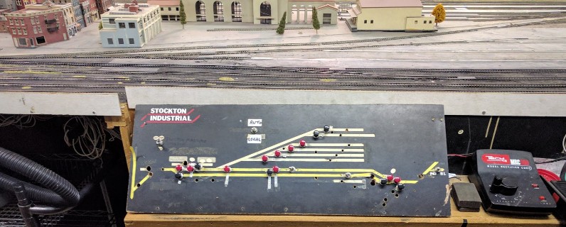
Track plan:
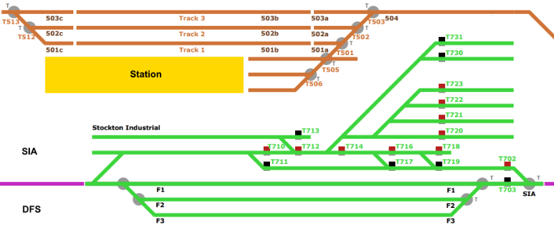
On this track plan, the purple line denotes the connection to the mainline & Stockton Yard on the West (left side) and to the branchline on the East (right side). The SIA is the part above the purple line and contains a track ladder. The DFS is composed of the 3 tracks labelled F1, F2, and F3.
It seems that the SIA was part of the original track plan, with the DFS tracks added later around 2009.
Operation:
- The SIA trackage is operated from the SIA panel, which is local to the yard.
- The DFS tracks are operated from either the Stockton Panel (West access) or from the Mountain Panel (East access). Both panels incorporate an interlocking seize/release mechanism to define which side has priority.
A fairly complex electronic module, designed by Mr. Perry, is located under the DFS and controls its power routing. Such power routing depends on the two interlocking F1/F2/F3 switches located on the Stockton Panel or the Mountain Panel, as well as in part on the interconnection between the branchline and the Stockton Station (controlled from the Passenger Station panel), and finally on the Auto/Local toggle on the SIA panel. A consequence of this design is that ironically one cannot really control the DFS yard when standing next to it.
In the current setup, special consideration needs to be taken about the rail polarity at DFS, as it is linked to the rail polarity of the branchline at Rodger Junction. The power to the branchline goes through a polarity inverter so it can be polarized either way. However the SIA and the mainline are polarized in a constant way, so these may not align based on which turnouts are selected at Rodger Junction. The current design was properly suited for a DC layout but is not logical nor expected for a DCC layout and needs to be simplified.
10- Fairfield Industrial Yard
10.1- Presentation
Right in the middle of the layout is a fairly large industrial city. When visitors walk in, it’s right in the middle visible above the Mountain Panels.
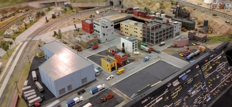
This represents the industrial park of Fairfield, California and includes a good portion of street running. It is not clear what year is represented. This was designed for switching. There’s a dedicated control panel in front of it (see below).
When I discovered the layout back in 2014, this part of the layout was not powered, and it is still not functional as of 2020. I had started looking at it back in 2015 and realized there would be quite some work involved in making it fully functional (as in “tedious but not impossible”). But does it need to be fully functional? Since the layout runs as an “automated exhibit” now 4 days a week, I just realized this area has some great potential for some simple but effective automation even within its current state, and that would add great value to the visitors. (Update: as of 2021, the panel has its own power district / circuit breaker and at least one section of track has been somewhat restored, pending completion.)
The track plan:
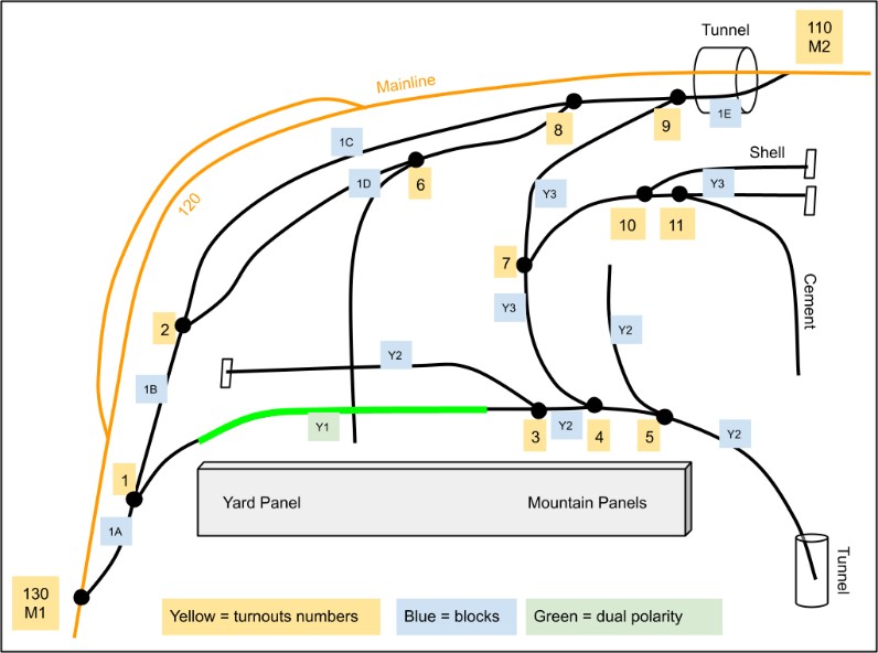
Blue labels on the track plan denote individually powered blocks. This was wired for DC and the green “Y1” section has polarity inversion which needs to be adjusted based on the state of the turnouts T1 and T4 (you can see that T1 - T4 - T9 form a delta Δ reversing loop).
The first track is nicely split in blocks: 1A, 1B, 1C, 1D and 1E.
The inner tracks are split in 3 blocks: Y1 is the reversing part, and Y2 and Y3 have different polarities.
The panel has a toggle to align Y1 either on the polarity of 1A or the one of Y3.
When trying under DCC, depending on the position of T4, I remember seeing either a short on the T3-T4 side or one of the T4-T5 side. Back in 2015 I did not quite manage to understand how that section was wired as a lot of the track feeder wiring is embedded in the sub-plywood.
In the blocks Y2 and Y3, a lot of the continuity seems to happen through the frog contact on the rails with no track feeders.
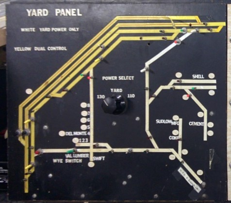
On the panel, the two first tracks in yellow at the very left with the barely-visible red line represent the mainline (block 120) and the Fairfield station siding (block 121). These blocks are controlled from the Valley Panel on the other side of the layout. The next two tracks in yellow are part of the yard and form a dedicated block.
Since this was designed for DC, the panel has a power selector to draw power from block 130 (turnout M1), or from block 110 (turnout M2), or from an internal power supply (when not joined to the mainline).
While in the process of remapping all layout blocks and turnouts to a consistent numbering scheme, numbers 900-930 have been allocated to Fairfield:
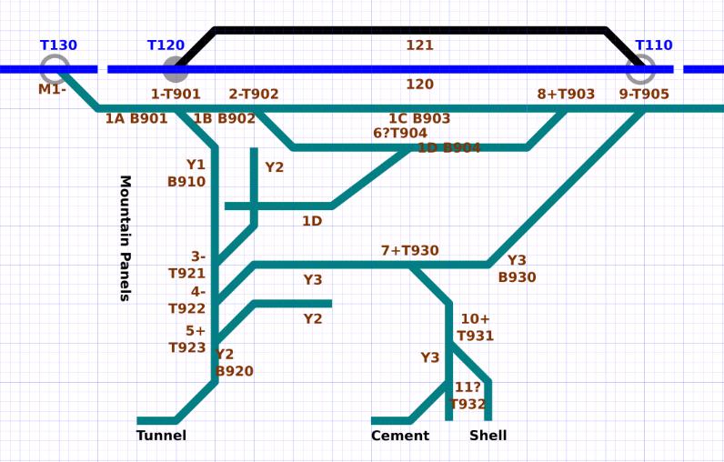
Notation on that schematic: for each turnout or block, we have the old local numbering scheme followed by the new “global” numbering scheme. The -/+/? symbols indicate if a turnout is known to work (- = not working, + = working, + = unknown). For example “4-T922” is turnout 4 in the older map, T922 in the new DCC scheme, and is known to be problematic.
Correspondence between older and new notation:
Blocks |
Turnouts |
|||
1A |
B901 |
M1 |
T130 |
|
1B |
B902 |
M2 |
T110 |
|
1C |
B903 |
1 |
T901 |
|
1D |
B904 |
2 |
T902 |
|
1E |
B905 |
3 |
T921 |
|
Y1 |
B910 |
4 |
T922 |
|
Y2 |
B920 |
5 |
T923 |
|
Y3 |
B930 |
6 |
T904 |
|
7 |
T930 |
|||
8 |
T903 |
|||
9 |
T905 |
|||
10 |
T931 |
|||
11 |
T932 |
|||
All the turnouts were unconnected when I started my examination -- when the layout had been converted to DCC, the turnout power bus had been switched from AC to DC (for tortoises); since these were still the original AC-only twin coils they had simply been left unconnected. I started by rewiring an AC bus to bring power to these twin coils, and then I proceeded on testing them.
Some would not throw, some did not close the rails properly, and some would not bring the right frog polarity:
Turnout |
Mechanical |
Frog Power |
Notes |
M1 |
Functional |
2015: Functional 2017: Not functional. |
2015: Was functional. Suggested adding a Seize / Release on the valley panel with light status. 2017: Frog wired to normal (was being resistive and stopping some decoders). |
M2 |
Not connected? |
No idea |
Seize / Release with light status would be required to avoid mishaps. |
1 |
Mostly OK |
Functional |
The board holding the twin-coil is loose, needs to be screwed properly. |
2 |
Gap, needs work |
Loose, needs work |
Above: Curved closure rail doesn't fully close the gap. |
3 |
Doesn't always snap |
Shorts when thrown |
Sometimes stuck and doesn't always snap towards the siding. |
4 |
Functional? |
Shorts + dead spot |
Shorts when thrown towards Y3 B930. |
Dead spot between 4 T922 and 5 T925 on the upper rail. |
|||
5 |
Functional |
Functional |
Power to siding seems to come from Y2 B920 via the frog, turns off when switched [must check] |
6 |
No idea, must check |
No idea, must check |
Seems ok when going straight (between 2 T902 and 8 T903), didn't try switching yet. |
7 |
Functional |
Functional |
Both sides tested OK. |
8 |
Functional |
Functional |
Both sides tested OK. |
9 |
Buzz, doesn't switch |
No idea, must check |
Block 1E B905 didn't seem powered, must check. |
10 |
Functional |
Functional |
Both sides tested OK. |
11 |
No idea, must check |
No idea, must check |
Was OK going straight, didn't try switching to cement factory. |
Status Color: Green: work done here // Orange: functional but needs work // Red: not functional .
10.2- Update to Block B905 & Turnout T110
Block B905 (aka “1E” in the old notation), is the track leading from Fairfield to Lodi, joining the mainline at T110 (aka “M2”).
Update 2020-12: https://www.alfray.com/trains/blog/randall/2020-12-21_an_update_on_the_lodi_maintenance.html
This block has been physically cut in two by a cut in the track after the tunnel output. The goal is to power half of it from the Lodi side and use it as a temporary spur / interchange.
Notation wise, from Fairfield towards Lodi, we have:
- T905 is the turnout in Fairfield,
- B905 is the Fairfield side of that track,
- B906 is the new block number for the Lodi side of that track,
- T110 is the turnout where B906 joins the mainline at Lodi.
Turnout T110, aka M2, was still powered by a twin-coil. There is also a corresponding turnout toggle on the Lodi panel, although the wires for it are not physically going anywhere.
The current effort is to convert T110 to a Tortoise, and then use a Digitrax DS64 to provide DCC power for it.
TBD Update upon completion; See Blog: Lodi Maintenance 2020-12-21.
10.3- DCC Power
The NCE EB1 circuit breakers for Fairfield and Stockton Station are now installed:
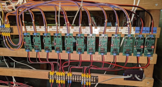
DCC is now provided to the Fairfield panel using a dedicated power district; it connects to a 2-position terminal in the panel and then feeds directly in the “Yard +/-” input on terminal positions 8-9:
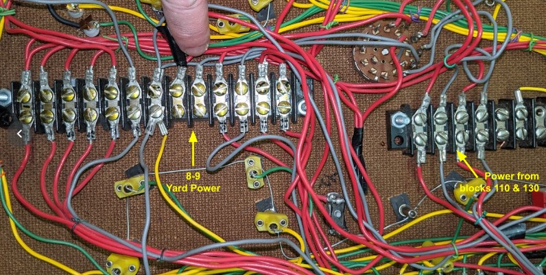
The power selector also receives power from blocks 110 & 130 for the interchange with the mainline. These are the 4 wires on the right-side terminal. These have been disconnected by shifting terminals to empty positions.
10.4- Fairfield Grade Crossing
The main two-lane cantilever grade crossing installed at Fairfield, between the Fairfield Station and the Fairfield Industrial Yard:
First run, before adjusting sensor sensitivity or timings -- works really nicely out of the box.
The control module is installed under the layout, just behind the Fairfield Industrial Yard panel:
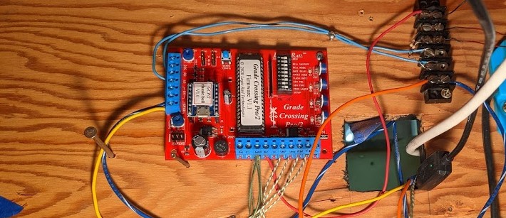
The speaker is installed next to the Fairfield control panel, with a toggle to cut off the sound as needed:
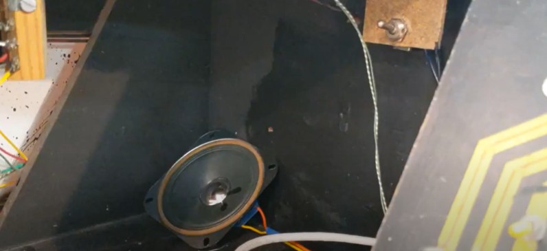
Each photoresistor was prepared with a little wire extension, that is mounted with a PCB 2-position terminal:

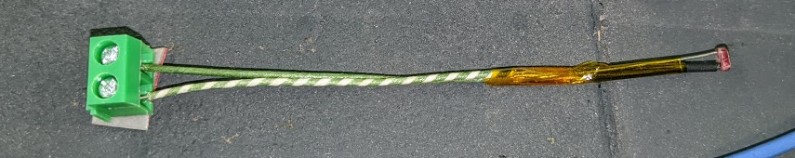
The leads off the PCB terminals are cut, and double-face tape is applied for mounting under the layout. Kapton tape is used to isolate both leads.
Under the layout, the terminal is just held in place using double-face tape. It makes it easy to then add the connection towards the GCP/2 module without having to solder:
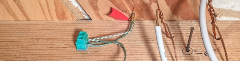
The wires leading to the photoresistors are somewhat rigid and help maintain the resistor at the correct height between the ties. Here are the four sensors locations:
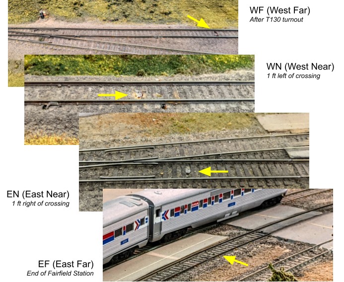
All the sensors connect directly to the module using twisted pair wire.
The cantilever LEDs are connected via a terminal which is used to insert the two 1 kΩ resistors in series.
One drawback of this cantilever is that it looks better when seen from the other side. It’s a dual-lane yet the lights on the left lane (where that orange truck is) are facing away from the layout viewers. It is of course more prototypical that way.
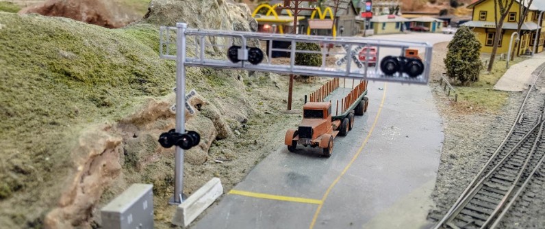
A future extension is to add a single-mast crossing light on the other side of the road, connected to the same control module.
One thing to remember is that if the overhead lights are not on, the crossing will activate and ring the bell. That’s the main reason why I put a cut-off switch next to the speaker. In the Randall Museum train room, we have different circuits for the overhead lights, and sometimes folks forget to turn them all on when opening the museum in the morning.
In case the crossing lights & bell needs to be disabled, we have two options:
- The toggle switch next to the speaker by the Fairfield control pane. This requires access to the Mountain panel area, which can sometimes be difficult when the museum is crowded.
- The whole module is powered via an extension cord connected under the Valley panel. This makes it easier to unplug the entire electronics module for the Saturday operators or the museum staff.
Note / future change: Consider moving the power brick under the Valley panel and have a long wire with low-voltage AC rather than a 110 V extension cord under the layout.
Details on the board used: a Logic Rail Technologies Grade Crossing Pro/2, a “Classic Bell” extension module, and a 4 inch speaker.
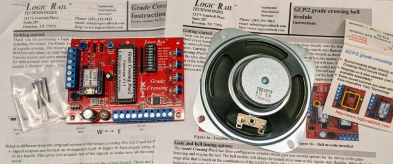
Details for wiring: A 110 V to 9 V AC power brick is currently used. It is connected to an extension cord that plugs near the Valley panel for “remote” control. Power can be 7-14 V AC or DC, per recommendation. Looking at the board:
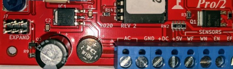
Just to the left of the AC terminal is a bridge rectifier. And just above that is a 7805 (IC1), a typical 5 V fixed voltage regulator. Marking indicates an On semi 7805CG RQL35, aka MC7805CDTRKG in Farnell or DigiKey. Nominally, input must be 2 V above output thus 7 V min per specs.
It is crucial to note that LEDs connect directly to the “+DC” terminal ⇒ they are powered at the voltage applied to the board (directly in DC, on the output of the bridge rectifier in AC).
Detail of wiring for photocells:
- WF = West Far / WN = West Near / EN = East Near / EF = East Far.
- Photocell locations reuse existing setup:
- WF = Just after the T130 turnout to Fairfield.
- WN = About ~1 ft to the left of the crossing
- EN = About ~1 ft to the right of the crossing
- EF = Just before the level crossing after the Fairfield station.
- As indicated above, photocells are wires with the little wire extension going to a 2-position PCB screw terminal.
- All screw terminals are double-side taped under the layout.
- The extension wire is hard enough to be used to hold the photocell at the right height.
- All wiring to the terminal at the bottom of the GCP/2:
- One side of the photocell to the corresponding WF/WN/EB/EF terminal.
- All photocells to GND terminal.
Speaker connection:
- 8 Ω speaker to the left terminal.
- 2 bottom positions are SPKR.
- There’s a pot under it to adjust volume.
We are wiring SceneMaster Walthers crossing signals.
From the SceneMaster Walthers instructions:
- Cantilever signal 2-lane (Walthers 949-4330):
- 3 wires (1 black, 2 red-black). There are 3 signals with 2 LEDs eachs on the mast/cantilever, thus I’d guess each wire controls one LED.
- Tested: The single black wire is the positive side of the LEDs, and the two red-black ones are the negatives.
- Signal instructions: LEDs rated for 1 V max.
- Signal instructions: Use “One 1000 ohm resistor on the black wire”. See below.
- Crossing flasher (Walthers 949-4333):
- There are 2 masts, with 2 LEDs each. One black and two copper/yellow wire.
- Signal instructions: LEDs rated for 2.3 V max.
- Signal instructions: “Black is the common ground”. See below.
- GCP/2 instructions are to use one resistor per LED instead of a single common one.
- I’ll use 1k Ω resistor, one per output (one per red-black wire, or copper/yellow wire).
- Connects to RO / LO on the left terminal block.
- The other side connects directly to the “DC+” ⇒ the LEDs are connected directly to the DC power supply or to the output of the AC bridge rectifier.
10.5- Future Plans
Suggestions:
- Install a separate DCC protection circuit so that shorts in the yard/city do not affect blocks 110 or 130 (done).
- Remove the block selector (the round 130/Yard/110 knob) and instead use an on/off switch.
- Add a separate on/off switch for the turnouts AC with light indicator when powered.
- Replace the Y1 polarity inverter (green switch) by an automatic reverser (e.g. frog juicer) as used on DCC loops (and remove the reverser).
- Some of the small sidings seem powered by the frog. Not really an issue as long as it's understood.
Fully restoring this section of the layout is not very high on my current task list. The location makes it extremely hard to use for switching when the public is present. However even in the current half-working state, it presents some interesting automation potential.
First let’s reduce the field to a known and manageable quantity:
- Let’s posit that the automation does not touch any turnout. They are placed in a fixed state. This simplifies a lot of things and avoids a lot of issues (especially when power routing is done via the turnout, never good for DCC block detection).
- Let’s posit we don’t use block detection in that case. Either infrared or some camera-based system is used.
- Let’s posit we use purely Y2 or Y3 blocks and “never cross the beams”.
Using these axioms, we can still do some basic shuttle-style automation:
- A small trolley can get out of the tunnel on the right bottom side and go up Y2 via T5. This stays on Y2.
- A small switcher with maybe one car could travel on Y3 via T7 and T10 or T11. There would be very little visual enhancement by trying to throw T10 or T11 to create some variety in the route, but it’s a substantial technical effort and may result only in a minor subtle change that most people may not notice; I’ll elaborate on that below.
- There’s some potential running on 1A-1E also in a shuttle manner with another switcher or similar.
- A better potential would be going from 1E to T8 / T6 and up to the Y1 crossing then shuttle back.
Suggested automated routes.
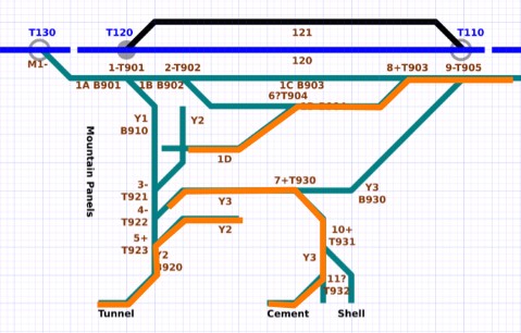
I’d call that “phase 1”: These are very simple linear routes, which could operate on a simple timer with the usual motion-activation trigger used elsewhere.
Actual control could be done locally using an Arduino or offset to the main automation computer. The idea is to treat the whole yard as a single DCC-controlled block and forget block detectors as the current electrical design is not at all well suited for it -- a lot of these rely on powering track via point closure rather than individual block power feeders.
Instead point-to-point detection using track-embedded infrared-reflectance detectors would be more suited, as I had experimented with a couple years ago. The other detection that would work well here is camera-vision based as we have a fairly compact field to monitor. Follow the links for technical details if interested, including pros & cons.
One could trivially define a “phase 2” with more advanced automation. As pointed above, if turnout control is included in the automation, there are more route choices. However it adds one more dimension in what can go wrong in the automation, and the result may be sub-par. Let me elaborate on this as it boils down to the usual most important question: “who is your target”. If the target is to entertain people who can appreciate the subtlety of a train changing tracks, it’s worth the effort. However if the target is to entertain bystanders who are fine with “stuff moves”, then whether a train changes track or not is lost in value. Yet it’s a major effort to move to that level. So it better be worth it.
If we remember this is a museum for kids and Saturday visitors, it’s best to have a simple repetitive automation that works flawlessly rather than a complex one which has more failure points.
11- Lodi
TBD 2020 description, changes, etc.
See Blog: Lodi Maintenance 2020-12-21.
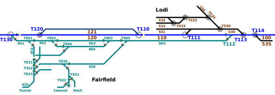
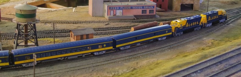
Lodi on the left, mainline (the dark rails in the middle), and the Fairfield B905 block on the right.
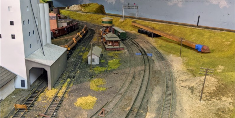
The Lodi control panel.
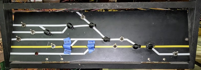
12- Napa Yard
TBD 2020 description, changes, etc.
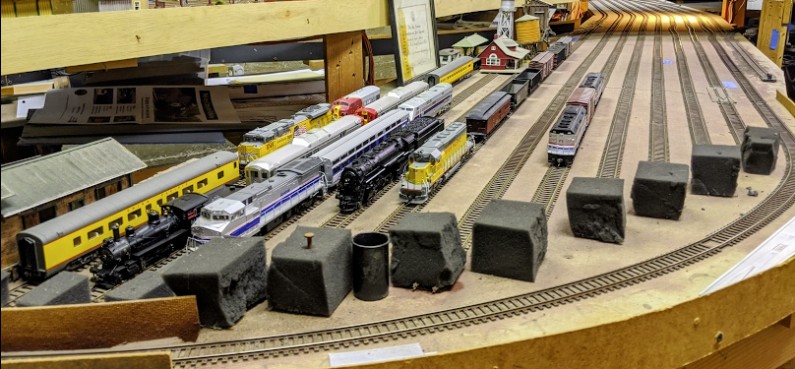
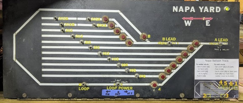
DCC auto-reverser on Napa Loop:
<TBD snap picture & detail wiring>
13- Richmond Yard
TBD 2020 description, changes, etc.
This area is actually composed of two yard -- a staging yard and a switching industrial yard. It is covered by 3 panels.
13.1- Richmond Staging Yard
The staging yard is on the center in this picture. The industrial yard is on the left, and the mainline is the little bridge on the right:
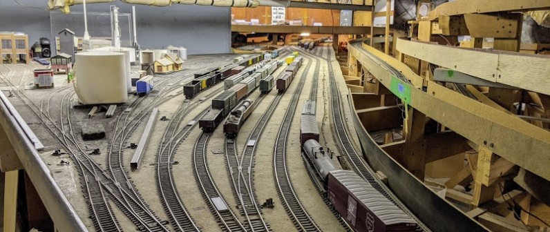
The yard has manual turnouts, and all frog power is done by contact of the point. This leads to a lot of frog power issues.
Access to the staging area from the mainline:

The blue labels are the result of an early attempt at labelling which toggles / turnouts are problematic, and where they are controlled from:
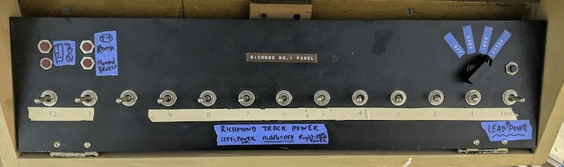
13.2- Richmond Industrial Yard
I don’t know if that’s the proper name for it, so I’ll name it this way. This area is obviously designed with local switching in mind:
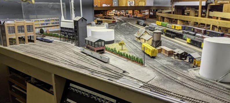
There’s a fair amount of detail in it:
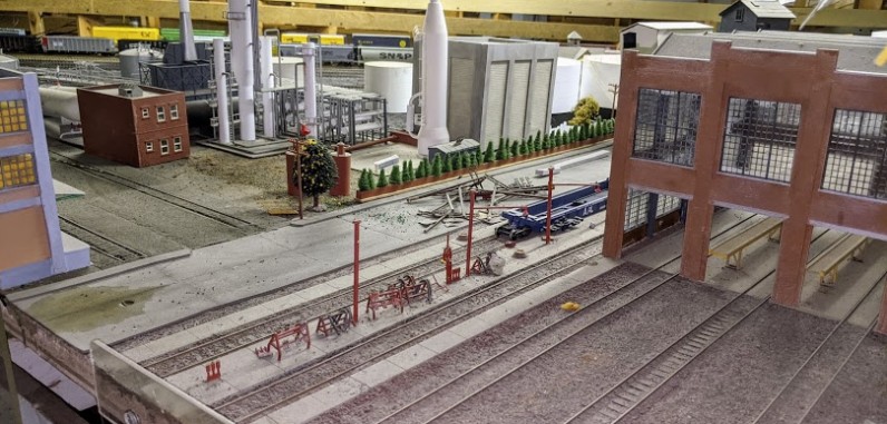
The first control panel:
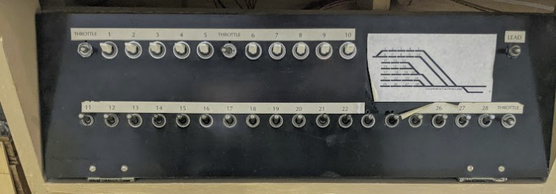
And the second one:
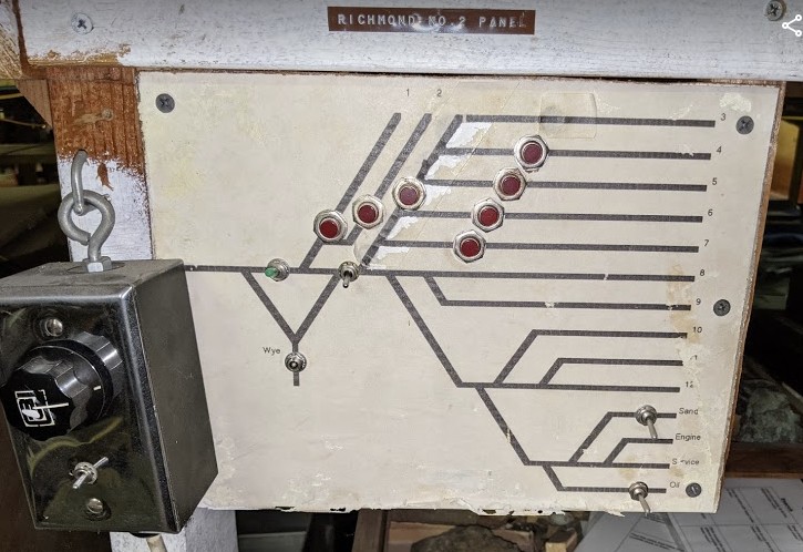
14- Bridgeport Yard
TBD 2020 description, changes, etc.
See Blog - 2020-12-06 - DCC control for Bridgeport Turnout,
Blog - 2020-12-12 - DCC control for Bridgeport Turnout, part deux
Blog - 2020-12-13 - Bridgeport Track Cleaning, Auto-Reverser for Balloon Track
Blog - 2020-12-23 - Bridgeport Auto-Reverser for Second Balloon Track
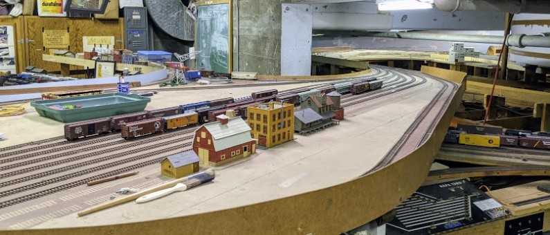
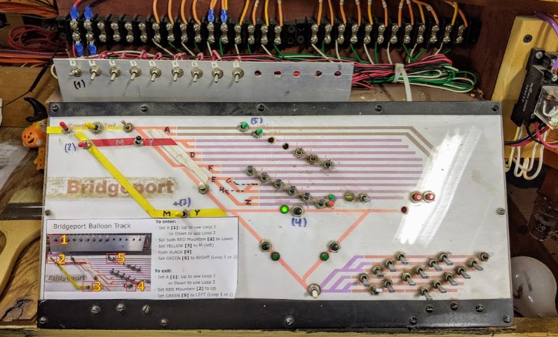
15- Branchline
The Branchline is an independent section of track. It is double-gauge for a portion of it. There is an interconnection with the mainline at block B322, which is called “Angels Camp”. On the other side, the Branchline meets the mainline again near block B311, this is named Rodgers Junction (or Rodger’s Junction, I’ve seen both writings around).
Initially I lacked a proper history behind the design of the branchline. However most of the names I found match California city names all located in the sierras just east of Sacramento, an area that saw a lot of activity around the gold rush era and spurred the creation of a number of small logging / mining narrow gauge operations. Digging a bit further, a good portion of names can be found on the map of Nevada County Narrow Gauge Railroad, a copy of which I found in archived documents in the layout.
Names which I found in old documentation, some taped under the layout, or on control panels, include:
- Angels Camp (often written as “Angel Camp”), the junction point to the mainline which is likely Colfax.
- Oilville, that name appears on the paper label under the layout.
- Chicago Park, very close to Colfax; that name appears on the paper label under the layout.
- Smith Flat town, which serves the “Gravel Pit” and the “Red Dog Mine”.
- Bear River is likely a reference to Bear River Pines which is next to Colfax.
- You Bet town.
- Greenhorn Logging Railroad.
- Colemans, which appears on the NCNGR map, is likely Coleman.
An engine that goes from the mainline (block 321) to the branchline will eventually return at the “Rodgers Jct” and can rejoin the mainline in the reverse direction. The full branchline is thus essentially a long reverse loop.
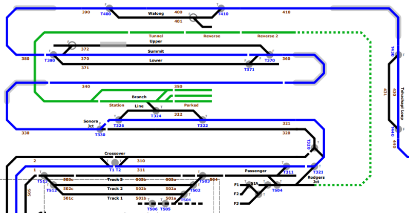
The branchline, denoted in green on this track plan
Based on various notes found, it is my understanding the Branchline was initially designed in 1967. The original plans called for a narrow-gage balloon track which was never finished (on the map above, it would have completed a circle from the “station” block to the “reverse 2” block). Further written mails indicate the “Narrow Gauge is ready to wire” in 1973~74. A latter new set of design documents date from 1990-91, and describe new wiring and panels (see 11.4- You Bet Panel below).
The wiring of the Branchline is somewhat inconsistent:
- The main branchline panel (a.k.a. “Angels Camp”) has power pickups for each yard track and clearly defined blocks for the track behind the Sonora station.
- The other panels of Smith Flat and You Bet also have clearly defined block boundaries.
- What happens to the track beyond these blocks is more uncertain.
- The single track between Angels Camp and Smith Flat seems to have a single feeder so it should be a single long block.
- The part between You Bet and the Rodger Junction is also to be considered a single very long block. There is one power feed just after You Bet than is also connected to a power feed up to the Rodger Junction. In between, especially around the loop by the old mine there are track feeders which were connected to something and have been cut off and left dangling -- or more likely have been prepared with the track and never connected to any power bus. All that part is apparently only powered via the track joiners.
15.1- Reverse Loop
The DC/DCC relay for the Branchline feeds a Lenz Digital Plus LK100. This is a “Reverse Loop” polarity inverter donated by Mr. Perry. According to the LK100 manual, it can support up to 5 A in the reverse loop.
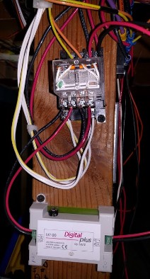
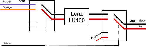
This is one case where the “double relay” scheme for the DC / DCC makes sense: the LK100 is powered by the DCC only when the relay is active for DCC.
My understanding by looking at the existing wiring is that the whole power supply to the branchline probably goes through the LK100. That is certainly true for the “main” single-track path of the Branchline. I am not sure what happens at the boundaries, the interchange tracks with the mainline (at least at Angels Camp, there are obvious power selectors between “Mountain” and “Branch” power).
Here’s an interesting artifact: as far as I can tell from schematics, the Red/Black feeder color pattern is inverted when the Branchline connects back at Rodgers. Since it’s a reverse loop, the common rail has to be opposite to the mainline at one of the two ends, and this happens at the Rodgers Junction.
This means some kind of polarity inverter is needed. From all what said above, my assumption (until proven wrong) is that all the “branch” power goes through that LK100, and I’d expect an engine entering at either Angels Camp or Rodgers would trigger the polarity inversion as needed. When this happens, the LK100 can certainly be heard “clicking”.
The current setup is certainly problematic as it means both junctions (at Rodger or at Angels Camp) with the mainline can have the same or a different polarity. This would definitely not work properly if two trains were trying to enter (or enter/exit) from the branchline to mainline at each junction at the same time.
The other problematic issue is that the inverted polarity, when present at Rodger’s Junction, also carries up to the main track at DFS as they are wired together via the DFS relays.
15.2- Branchline Main Panel
The branchline panel is hosted in a sliding drawer:
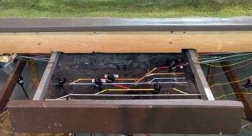
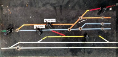
Under the panel is a terminal block connected to the various toggles:

This in turn connects to another terminal block on the frame of the layout, which comes with a clear label for each terminal position, as seen on the right. Not all positions on the terminal are used. Some have wires which have been cut or lead to nothing. Each number corresponds to one toggle, as depicted below: |
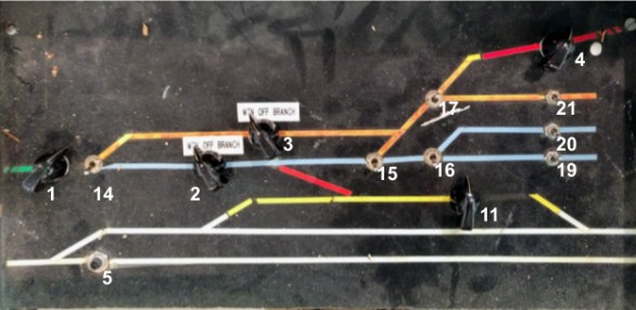
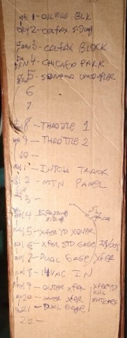
Track diagram (blue is mainline, green is branchline):

Label |
Usage on Panel |
Block or Turnout |
Wire color to drawer |
Wire color on layout |
|
1 |
Oilville Blk |
Rotary Toggles with
On #4, the right side wire to Throttle 1 is broken. |
B830? |
White |
Orange + Blue/White |
2 |
Colfax Siding |
B821 |
Gray |
Green (AIU 48:2) |
|
3 |
Colfax Blk |
B823? |
Faded Orange |
Red |
|
4 |
Chicago Park |
Drab Brown |
White/Blue |
||
5 |
Sonoma Uncoupler |
Not connected to push button |
Faded Orange |
X |
|
6 |
-- |
-- |
NC |
NC |
|
7 |
-- |
-- |
NC |
NC |
|
8 |
Throttle 1 |
Throttle 1 |
Faded Green |
Red (block power) |
|
9 |
Throttle 2 |
Throttle 2 |
White |
Red (block power) |
|
10 |
-- |
-- |
NC |
NC |
|
11 |
Intch Track |
Rotary toggle, wired like #1-4 |
B322? |
X (broken) |
X |
12 |
Mtn Panel |
Not connected to panel |
Blue |
X (see note) |
|
13 |
-- |
-- |
NC |
NC |
|
14 |
E. Passing Siding |
SPDTs using power from #18 (14 V AC) via 2 diodes to control Tortoise motors. On 14 (T830), point is broken/missing and throw bar has been spiked to prevent from being thrown. Label groups all of these with “In/Out Xfer” |
T830 |
Drab Brown |
Brown |
15 |
Xfer Yd Xqvpr |
T820 |
Black |
Gray |
|
16 |
Xfer Std Gage |
T810 |
Black |
Black |
|
17 |
Dual Gage |
T821 |
Faded Blue |
Green |
|
18 |
14VAC IN |
Label “14 V AC” (actually 12 V AC) |
Faded Yellow |
Yellow (AC power) |
|
19 |
Outer Xfer |
SPDTs for sidings power. Label groups all these with “Xfer Yd Kill Switches” |
B801 |
Gray |
Gray (AIU 48:1) |
20 |
Inner Xfer |
B802 |
Black |
Brown (to AIU 48:2) |
|
21 |
Dual Gage |
B803 |
Faded Green |
Green |
X = there is a lead in the terminal screw that is broken.
NC = the terminal screw is not used at all.
Notes:
- Position 11 is obsolete and not used; power from this siding is controlled by the Mountain Panel block 322.
- Position 12 on the terminal block on the layout is used to connect a red wire to a red wire from a completely different circuit that has nothing to with the branchline drawer. Under the drawer, the wire is cut.
- Position 18 connects to a bus labeled “14 V AC” (which measured 12 V AC). For each turnout toggle, an SPDT selects one polarity of the AC power using a diode. This matches the “Tortoise wiring using AC with Steering Diodes” (PDF here):

- The Tortoise AC power bus likely comes from the 6/12/24 V power supply next to the NCE command station.
This schema, rebuilt from one of Mr. Perry hand-drawn schematics, details the power routing of B322 which is the interchange track between Mainline and Branchline:
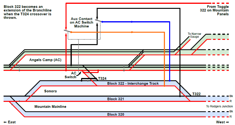
Let’s look at what’s going on. Remember this was designed to work in DC, and trains speed is directly affected by the voltage on their track. In the case of a train that wants to move from the mainline to the branchline:
- Step 1: Throw T322 to move train from block B321 to B322. By default, B322 is powered like the mainline, and the 322 toggle on Mountain Panels 1 or 2 can be used to dictate which DC throttle is used on the mainline -- obviously the same as B321.
- Step 2: Realign T322 once the train has fully entered the B322 interchange track.
- Step 3: Throw T324. The “Aux contacts” on the AC (Angels Camp) switch machine side of T324 change. This powers block B322 from the branchline block B830. The desired DC throttle can be selected on the Branchline Panel (Mountain, Off, or Branch).
- Step 4: Realign T324 once the train has fully entered the B830 at Angels Camp.
15.3- Smith Flat Panel
This panel controls the section of Branchline between both tunnels. The two main blocks are “Smith Flat Block” and “Bear River Block”. One spur serves the “Gravel Pit” and the “Red Dog Mine”.
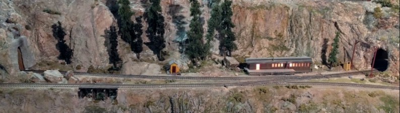
Front |
Back |
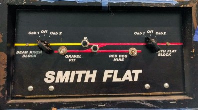
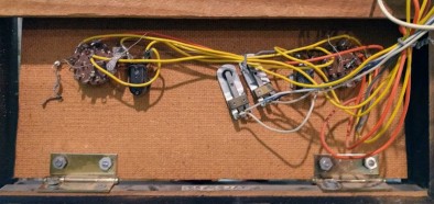
The panel connects to not one but two terminal blocks.
One terminal just above the panel on the wall, which in turns feeds another terminal connected to the layout.
Some of the wires delivering power are not on the second terminal, they come directly from the first terminal.
Terminal #1 from panel: |
Terminal #2 to layout: |

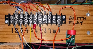
Here is the panel annotated with the terminal positions (from left to right):
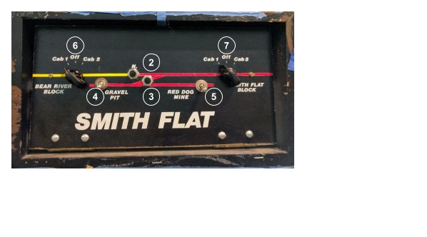
To Terminal 1 |
To Terminal 2 |
To Layout |
Usage |
|
1 |
White |
White |
NC |
Power to N/P turnouts, comes directly from somewhere else |
2 |
Blue |
Blue |
Blue + Wh/Blue |
Turnout N (normal) |
3 |
White/Blue |
White/Blue |
Blue + Wh/Blue |
Turnout P (divergent) |
4 |
Yellow |
Orange |
Orange + Red |
Toggle to power for Gravel Pit (power feed by #7) |
5 |
Yellow |
Yellow |
Orange |
Toggle to power for Red Dog Mine (power feed by #7) |
6 |
Orange |
Orange |
Yellow |
Output of the Bear River Block cab selector. |
7 |
Red |
Red |
Orange |
Output of the Smith Flat Block cab selector. |
8 |
Yellow direct to Red |
NC |
Orange + Gray |
Source Power for Cab 2, used by #6 and #7. The Red wire from the Mountain Tower comes directly to the terminal 1. |
9 |
Orange |
NC |
Orange x 2 |
Source Power for Cab 1, used by #6 and #7. There an Orange wire on the terminal 1 that comes from somewhere else. |
10 |
Gray |
NC |
NC |
Connected to main DC bus ground wire, for lights. |
Notes:
- Positions 2 & 3 connect directly to two twin-coils for the spur turnout. On terminal 2, there are 2 wires for one twin-coil motor and 2 wires (inverted colors) for the other twin-coil.
- The rod for the Turnout N is not connected.
- Either twin-coils do not work with the current power -- it’s the same issue as the Industrial City section, when tortoises were added, the power bus was changed to DC to work with the tortoises and does not adequately power the twin-coils anymore (these are AC coils).
- Disconnecting #7 (the Smith Flat Block cab selector) removes power to the whole front of the Branchline, up to the station and the sidings! That is certainly unexpected.
Updates:
- The panel has been disconnected from the layout as part of the renovation.
- Positions #6 and #7 are fed by #9 (cab 1).
15.4- You Bet Panel
This panel controls the section of Branchline after the small You Bet town in the back of the mountain.
In this part, the narrow gauge forks and connects back on the dual-gauge branchline as an unfinished reverse loop.
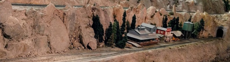
Front |
Back |
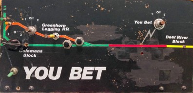
Now we have a name and a date for the panel.
This one connects to a 20-position terminal… using wires all of the exact same color :-/
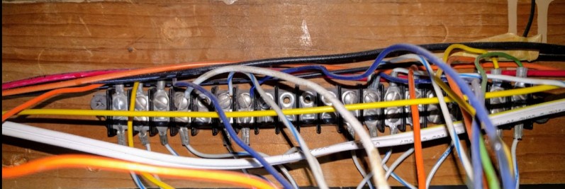
Here is the panel annotated with the terminal positions (from 1 left to 20 right):
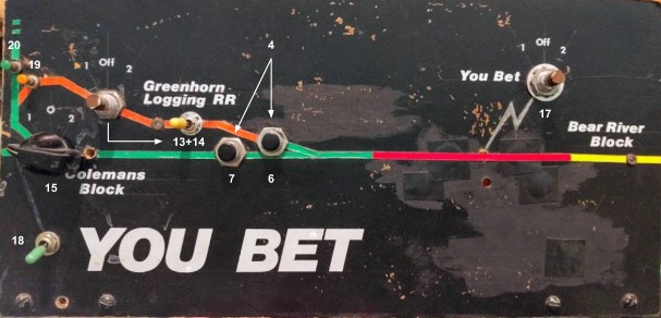
To Layout |
Usage |
|
1 |
Orange |
Power from Cab 1 |
2 |
Yellow |
Power from Cab 2 |
3 |
Blue |
Common / Ground for lights |
4 |
White |
Power for turnouts 6 / 7 |
5 |
Not Used |
|
6 |
White/Blue |
Output of turnout divergent to narrow RR |
7 |
Blue |
Output of turnout normal to branchline |
8-11 |
Not Used |
|
12 |
NC |
Wire from panel is connected to terminal but not used. Can’t tell what it does on panel either. |
13 |
Blue + White/Blue |
Output from Yellow polarity inverter. One of the inputs comes from the output of the Greenhorn Logging RR cab selector. |
14 |
White |
|
15 |
Orange |
Output from Coleman Block cab selector ⇒ Source for toggle 18 |
16 |
Not Used |
|
17 |
NC |
Output from You Bet cab selector |
18 |
Orange |
|
19 |
Yellow |
Output of orange push button / turnout divergent towards logging RR |
20 |
Green |
Output of green push button / turnout normal |
Updates:
- The panel has been disconnected from the layout as part of the renovation.
- Position #1 (cab 1) has been connected to #15 (Colemans Block)
16- Changes from GGRMC to Randall
In section 2- A Brief History, I explained how the layout was built by the GGMRC (the Golden Gate Model Railroad Club) and donated to the Randall Museum at the end of 2015. This section elaborates on the changes done to the layout as part of being the “train room” or “train exhibit” or “railroad model exhibit” (the nomenclature varies).
16.1- DCC Conversion for Automation
I did not convert the layout to DCC and don’t take credit for doing so -- this job had already been done by a few dedicated folks from the GGMRC who did an excellent job.
However my goal from the beginning has been to simplify the wiring and remove unused equipment.
As explained above, the layout has a complicated power scheme where track power can come from a variety of power sources such as DC custom-made power packs, DCM (a type of DC power supply), MRC walk-around radio control (also a type of DC power supply), and finally the DCC output of the DCC command station or boosters.
When the GGMRC club was running the layout back in 2014, it was mostly running in DCC mode. The layout was switched to DC mode a few times a year to run the Junior Engineer Day events, and I only knew of two people who knew how to transition that. There was no written explanation nor any visual indication of how to do it, and now that I have spent time understanding the wiring on the layout I can figure why it was not common knowledge, as it is a daunting and confusing task that was mostly done using trial-and-error.
When I took over, I decided to drop the DC part of the power scheme. The layout is to be run solely in DCC for automation, and having multiple systems actually creates issues -- maintenance issues as well as operators’ confusion. There is a lot of DC-related equipment (e.g. power supplies) on the layout that are not being used. There are a lot of power toggles/selectors that must be kept in precise positions for the current layout to be properly powered. We regularly get operators that would brush against a power toggle and involuntarily invalidate whole panels. Moreover they do not realize they do so, lack knowledge to recognize, understand, and rectify the issue.
Thus my goal has been to slowly simplify the system and this section will describe what has been done and what’s left to do. This is a philosophy goal. We need to realize that folks who are the most likely to operate trains on these club layouts come to enjoy their trains; they do not want to be electrician experts or computer experts. We also need to anticipate that at some point troubleshooting will be needed. The other aspect is documenting. Technical documents like this help yet are not read by end users. However simple labeling of toggles and switches should help, especially for troubleshooting and to convey instructions.
[TBD expand and link to other relevant parts of this doc: dc supply changes, understanding panels, labeling effort]
16.2- The Window Barrier and Fascia
[TBD]
17- Automation Overview
Up to 2015, the layout was open to the public only on Saturdays when GGMRC members rain their trains for the benefit of the public. For various reasons out of the scope of this technical document, in late 2015 the club decided to dissolve and donate the layout to the Randall Museum. Prior to this, the museum had made a requirement of having the layout run under some kind of automation when the club was not present, although very little details had gone into this.
After several months, in 2016, Jim Evans and I went back to see the museum staff and offered a plan to revitalize the layout using automated runs during week-days and operators running their own trains on Saturdays.
17.1- Initial Automation Proposal (2016)
The initial proposal was essentially a follow up to the museum requirements during their contract negotiations, but without making it a requirement as now it was on a best-effort basis.
The initial proposal outlaid some key points which I always kept further on:
- The layout would operate on DCC (and DCC only, no hybrid DCC/DC).
- No visual change to the appearance of the layout or the main control panels (the latter would prove problematic).
- Using off-the-shelf components (in this case NCE electronics compatible with their command station & cab bus).
- All the customization happens in dedicated software running on standard laptops.
- Automation mode would always be compulsory and would not prevent operators from manually running DCC trains.
- Education on the fact that model trains are prone to derailments and such mishaps. There is no strong guarantee on long term consistency that can be offered here. They require constant monitoring.
My initial vision regarding automation was complete control of the mainline, with sensors on every single block and every turnout controlled in DCC. With some creative software dispatching, it would trivially allow for long trains to run on the mainline, and even allow trains to run in reverse directions, stop and meet at sidings. However we knew the layout had issues mostly in the form of deferred maintenance, some sidings were not working, some turnouts were simply not functional. It thus seemed more prudent to offer a more limited mode of automation at first, and that’s what this proposal was about.
The initial proposal incorporated five automated areas:
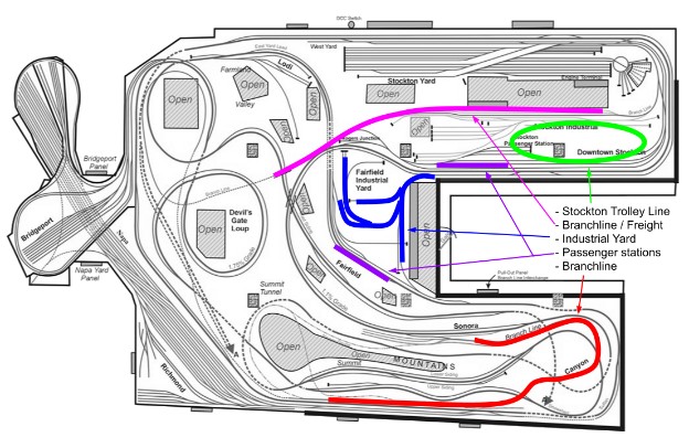
- A shuttle on the Branchline.
- Either a shuttle or a continuous run of a passenger train between the Stockton Station and the Fairfield Station.
- A shuttle of a freight train between the branchline and the DFS/SIA yard.
- One or more automations in the Industrial City yard.
- Having a trolley car circling in a modified Stockton area was offered as it was one of the requirements that the museum wanted during the contract negotiations. I did argue it would be expensive due to the need to rework scenery and personally I did not think it had much of an interest visually as the area is not very large.
- Optional, adding a continuous run of one or two more freight trains on the mainline, which could pass the passenger train when stopped at the stations.
17.2- Revised Automation Proposal (2017)
After discussion with the museum direction, we decided to narrow down the scope of the automation. This was a wise choice as we had argued that most of the proposal, although fairly sound technically, basically rested on unproven methods. One of the obvious points that emanated from the discussion was the whimsical desire for this to run in a fully automated and more importantly unmonitored mode.
It was thus decided to narrow down the automation to only 3 routes, as defined:
- The back-and-forth train on the branchline (pictured in red on the map below)
- A back-and-forth passenger train on the mainline between Stockton and Summit (purple route)
- Automation for the DCC Junior Engineer Day (green route)
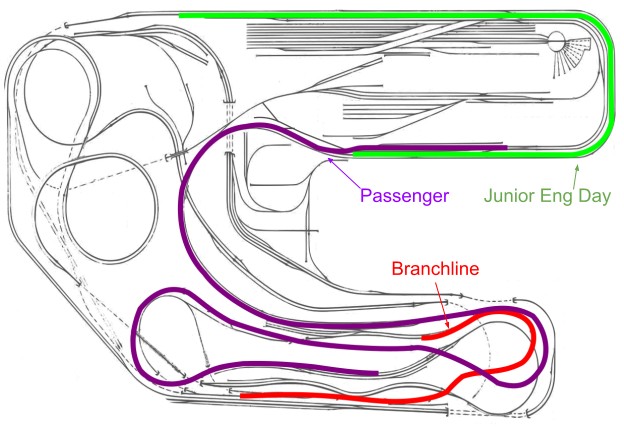
It was also decided that the automation would start when museum visitors (aka kids) would push a button on the fascia of the layout.
Based on this, I determined an approximate overview the parts of the layout that needed to be automated:
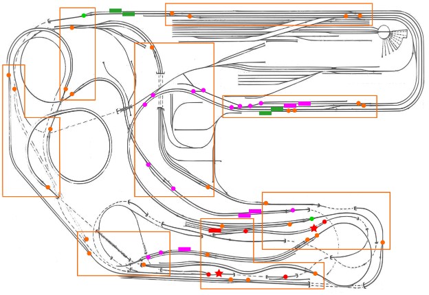
Legend:
- Dots represent turnouts that need to be automated. Red ones are for the branchline automation, purple ones for the passenger automation and green/orange ones for the Junior Eng Day.
- Red stars indicate points in the branchline that would need infrared sensors for train reversal.
- Rectangles indicate which blocks would need block detectors to detect the presence of trains. Purple ones for the passenger automation, red for branchline automation and green for the Junior Eng Day automaton.
For further simplification, we decided to first focus on the so-called “Passenger” and “Brancheline” automations and defer the Junior Engineer Day for later. The point of the JED, as initially run by the GGMRC as a club, was to have kids operate a train throttle, which required supervision. Instead here they would control departure of the trains by pushing a button, with no supervision needed. Another realization is that the JED requires the trains to do the full mainline loop, and they are hidden at least 50% of the time. Instead we defined a shuttle “back-and-forth” Passenger train that would be visible 90% of the time or more.
Trains were to be activated by two large buttons located on the fascia, one in front of the Stockton Station and one next to Sonora where the Branchline train stops. Computer control is used to ensure the buttons only activate the trains once they have finished their automation cycle and that they are idle back at their starting location. When the trains were running, pushing the button would activate the horn of the running train.
17.3- Updated Automation Proposal (2018)
The automation scheme presented in the previous section was implemented and used as-is when the museum reopened to the public in February 2018. We quickly learned the following:
- Although the activation buttons were only active when the trains were stopped at the station, kids would still push them even after the trains at left. At first this was used to blow the trains’ horns and that feature was quickly turned off as the buttons just kept being constantly pushed.
- Even after adding signs clearly indicating that buttons were only to be pushed when trains were back at their station, kids still bashed these activation buttons energetically as if they were punching bags. Surprisingly none of the buttons broke, but this made considerable noise and was quite disruptive especially when automation was turned off.
- The first day the Passenger train ran pretty much continuously for 8 hours, and one of the motors ended up smoking.
To solve this, we made small modifications:
- On the Passenger route, two trains were introduced. They take turns, leaving in alternance once activated, with a one-minute pause after they come back. Each run is about 5 minutes, meaning each engine works less than 50% of the day.
- On the Branchline route, the train was slowed down with a 10-minute pause before leaving again.
- The activation buttons were removed and replaced by an infrared presence detector. The sensor is tuned so that people moving towards the trains activate them. However trains are not activated if people just pass by the corridor and do not approach the trains.
- A tablet clearly shows the state of the automation -- whether it is working or stopped, and whether the trains are ready to go or resting and for how long. This helps considerably in reducing mishandling of the equipment.
17.4- Further Automation Proposal
I plan to add the following automation routes at a later stage. The dates below indicate when the project was proposed. I do not have any completion timeline at this point.
Trolley animation, behind the Stockton Town (2018):
See description at https://www.alfray.com/trains/blog/randall/2018-11-22_more_automated_routes.html
This would be a simple shuttle animation on a spur, with no turnouts, on a fairly short route.

Fairfield Industrial animation (2018):
The idea is to have one or two simple shuttle animations with a little trolley and a little switcher going back and forth on a closed route. There would be no turnout control.
See 10.5- Future Plans in the Fairfield section for more information.

Both trolley automations have in common that I’ve been considering not using block detection to control the trains. Instead I’d experiment with the “Software Defined Block” project I’ve started in 2023.
Valley Mainline Automation (2023):
This project is about running automated trains on sidings of the Valley Mainline, between block T151 (Napa/Richmond siding, or Sultan siding), going to the Fairfield Station siding (current inop), and up to the Timber Creek siding, stopping at the B71 siding just before the return tunnel.
In this automation, a train would be stopped on the siding at Sultan, and would take the valley mainline up to the Fairfield town, before continuing. It would zig-zag between the mainline and the sidings. A control toggle would allow Saturday Operators to disable the automation, in which case the train would be stored on the siding.
This project would use regular track block detectors and would require adding sensors to a good portion of the valley mainline, as well as turnout controls.
As a prerequisite, we would have to fix some of these sidings. The Sultan one, as well as the Fairfield station one, are currently inoperable (one has a potential dead spot, the other a dead turnout motor). On the plus side, it would maintain road activity on these sidings and prevent them from oxidizing. Right now these tracks need a lot of cleaning.
18- Automation Principles
18.1- Rules
The automation implementation follows these rules:
- It integrates with the existing DCC wiring of the layout and does not interfere with it.
- Each route can be disabled so that the layout can be used with or without the automation.
- In no way should the automation prevent from running trains "manually" on the layout using DCC.
- The automation will set the proper DCC-controlled turnouts in the correct position when starting yet these are not locked. Operators can still operate them as usual.
- There is no change in functionality to the existing panels.
- Off-the-shelf components are used when possible.
- The layout can no longer be run in DC. It operates solely in DCC.
18.2- Implementation Phases
The original plan required implementing 3 automation routes. My desire was to use an Agile method with iterations, a technique often used in software design, with the goal of getting results upfront as soon as possible.
The original idea was to split the implementation in phases:
- An experimentation / validation phase (to validate the techniques described here),
- A phase of "must have" work leading to an MVP (minimum viable product, see below),
- One or more phases of "good to have" work.
When work started, the effort was fairly unquantifiable. There were a lot of unknowns, and the role of initial "experimentation phase" was to find these issues as early as possible. When the project was started there was also a lack of visibility concerning access to the museum and how long things would take.
One common technique used in "agile" software development when dealing with unknown quantities is to define an "MVP", which stands for "minimal viable product". This defines the bare minimum features that a software must have to be deemed usable. The same principle could be used here, with a "minimal viable" implementation versus what is "nice to have". For example, automated turnout control is not mandatory -- we could have museum staff that must make sure turnouts toggles are set a certain way in the morning -- but it is fairly error prone and thus automated turnout control is deemed important yet not absolutely mandatory. If the time constraint had become a bottleneck, such control could have had been added after the museum opening date.
This explains why 3 main phases were set up: early experimentation, minimal implementation, and finally all the "nice to have" work. The obvious and common downside of that technique is that as soon as early results are visible, management often wonder why there is still work going on.
In our case, the first thing to do was define what should be the minimal viable product (MVP) appropriate for this project. Here this was defined as the minimum we had to deliver to consider the automation usable when the museum was to reopen, even if not ideal. This was defined as:
- The automated route for the passenger automation and the branchline with the desired engines going up and down the reversible path.
- This required sensors for the beginning and the end of the route, whichever form they would take.
- Turnout control was considered a "good to have" and not critical. Worse case scenario, a checklist could be given to the maintaining staff asking them to make sure turnouts are positioned in the correct way.
- Safeguards were considered a "good to have", which is adapting the automation to comply with whatever unforeseen situation that arose during the development.
- The Junior Engineer Day automation was a "good to have". Worse case, this could be implemented after the museum reopens to the public, or not at all as it is fairly inconsequential.
The phases were originally planned to be flexible -- the important part when splitting a project in tasks is to be able to re-evaluate these tasks as the project gets progressively implemented. New requirements may arise and some previous requirement may become obsolete.
And indeed, here tasks have not been necessarily implemented in the original planned order; instead they have been as it made sense (e.g. depending on complexity and mostly available equipment); the tasks list has been deliberately reorganized as needed.
18.3- Technology
Before digging in the details of how the automation is implemented, this section is mostly educational and it gives some background on the kind of equipment selected for this automation project. I keep this section voluntarily simplified, without digging into too much technical details to make it more accessible.
There are obviously many ways to runs trains and do automation. Model trains can run in DC (the old block-based electrical system) or in the more modern DCC (Digital Command Control).
Without going into the details of the DCC system, a short technical introduction is desirable. A DCC system needs at least two components:
- A “command station” which provides power to the track and at the same time sends binary digital data onto the track.
- Each locomotive contains a microcontroller called a “decoder”. The decoder gets the power from the track and also receives the binary orders sent by the command station.
- Each decoder has a number assigned to it, and this is how the trains are identified by the command station. All the trains are powered all the time, yet will only move according to the orders from the command station matching their numbers.
As an example, let’s say two locomotives are placed on the track, programmed respectively to numbers 10 and 6019. The command station can tell engine #10 to move at speed 5 forward, and engine #6019 to move at speed 10 reverse. The trains will move, wherever they are located on the track, as long as they can receive the power and the binary data through the rails.
The DCC command station controls more than just the speed and directions of trains. Our engines are sound-equipped and produce fidel representations of real engine sounds, with engine startup sound, engines accelerating, horns, whistles, and bells.They also have lights such as front lights, reverse lights, and red “marker” lights. All these can be independently activated, and more importantly they can be controlled by a computer.
This automation proposal is based around the principle of running the layout in DCC. The layout uses the NCE brand of digital controllers and command station and this proposal follows with the same brand of automation components to maximize compatibility.
Automation requires three different aspects: detection/sensors, control of turnouts, and a way to connect all these to a computer running the control software. Here's a schematic overview, which details will be discussed below:

I will elaborate on the following main points below:
- Overall philosophy.
- Control (the Computer / JMRI part of the schema above).
- Train detection (the block detector / infrared sensors part of the schema above).
- Turnout control.
18.4- Automation Philosophy
There are many ways to perform automated movement of trains on a layout.
Both the mainline and branchline automation proposed are point-to-point animations: a train moves from one spot to another and then reverses. The problem is fairly linear and seemingly easy to solve.
The naive approach often considered is to rely on timers, that is have a train move a certain distance for a certain time at a given speed, reverse, etc. Although simple, there are a few issues with this method. First, analog electric motors are not precise, even when operated using a digital system like DCC, and the back-and-forth operation makes the train stop at slightly different spots each time.
Another approach is to rely solely on sensors such as block sensors and point-detection sensors (optical or mechanical). One issue is that it implies wiring a lot of sensors into the track. This is nice since it allows software to have a complete sense of where trains are located on the layout and be in full control (at least in theory, see sensor limitations below). The paradigm often breaks when an inconsistency arises and the software doesn't know how to handle an unknown situation. A good example of this behavior is RocRail, a train automation software commonly used in some places. The issue with that software is that it acts conservatively and simply halts all the trains till any unknown situation is resolved manually.
My philosophy is to use a loose mix of sensors and timing.
For each repetitive route we want to automate, block sensors are used at the start and the end of the route such that the software can know for sure when the train has reached its destination in either direction. These block sensors dictate when a train can start, accelerate, slow down at destination and reverse. Some other block sensors can be optionally added, where important.
For less essential functions such as blowing the horn next to a station, timers are used.
Even within the scope of block detection, timers are used. Blocks, as used on this layout, are fairly long and the train will travel several seconds within the same block. So for example speed control at the Summit, where the passenger train must reverse, uses a mix of block sensing and timers: once the train enters the block, it waits 8 seconds before slowing down, then waits 3 seconds before starting its journey back, first at slow speed then accelerates after a dozen seconds -- the initial slow speed on the reverse journey is needed to clear a potentially problematic turnout, but it's not critical to know the precise spot where the train picks up speed, simply having it done a dozen seconds later is enough to clear the switch and that avoids one more sensor wiring.
The mix of blocks detectors and timing means we can have a fairly rich animation that happens at precise points on the layout. The timings might fluctuate a bit but the point where time is measured is reliable.
As for hardware, I selected to use off-the-shelf components wherever possible. These days it's trivial to make custom electronics boards and to create fancy contraptions using Arduinos or Raspberry Pi computers. I've certainly done that. One issue with custom-made designs is that they are, well, custom. It takes more time to design them up-front. When an Arduino board breaks down for any reason, another one must be bought and then flashed again with the same software.
In an automation like this, there will be many such components -- boards for block detection, boards for turnouts control, etc. That would mean several custom boards to design and manufacture and maintain.
The alternative is to use off-the-shelf components. As indicated above, NCE makes a nice range of such devices. They have BD20 block detectors that connect with 2 wires to AIU01 boards. These in turn are connected with a simple cable to the cab bus. Similarly they have Switch-8 boards that control up to 8 turnouts with direct DCC interface. Each individual board is a bit more expensive than the raw materials needed to make a similar board using an Arduino but we save a lot of design time and, most importantly, are easy to replace -- if in the future any such board fails, the museum can just order exactly the same board from the NCE web site and easily replace it by just rewiring the new one in place.
However the desire to use off-the-shelf component is not a strict requirement. Standard off-the-shelf components will be privileged where it makes sense and custom solutions will be used when there are no other known viable alternative or cost would be prohibitive.
18.5- Control
To control automation, typical choices are embedded boards such as Arduinos or using a computer.
There are several software packages available for computer-based control.
For this project, I chose to run the JMRI software under Linux on inexpensive laptop computers as I’ve done many times before.
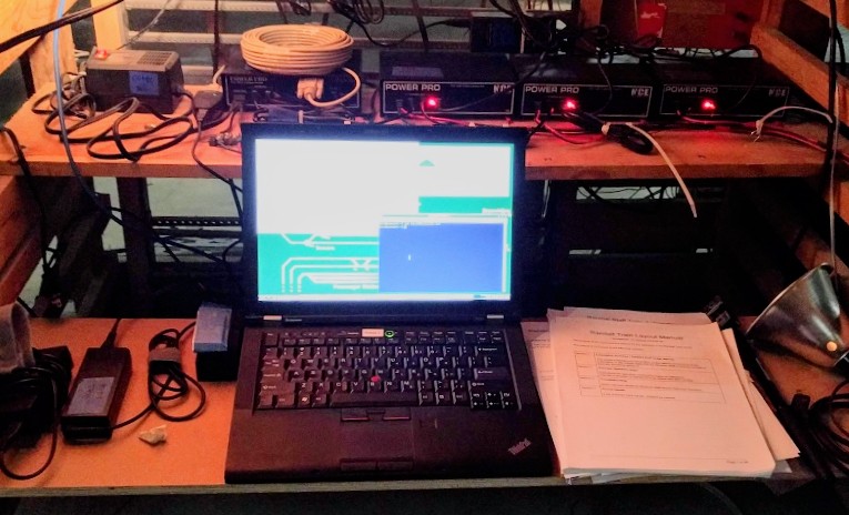
Laptops are very convenient since they combine a battery, screen, keyboard, and USB ports all in a compact form factor that is easy to place somewhere on the layout out of the public sight. My selected choice is to use refurbished 4- or 5-year old laptops, and I like to standardize on Lenovo Thinkpad T410/420; these units are commodities easily found on eBay or Amazon for very reasonable prices; they offer adequate levels of performance. These laptops must be considered as shells -- if the unit dies, it just needs to be replaced by a similar model and the only work needed is to move the hard drive from the old to the new one. Linux makes it trivial to mirror the drive and have a copy of it, in case the drive dies.
Not all laptops are designed to be "repaired" (some are really hard to open); the older Lenovo Thinkpads are sturdy, easy to replace, well designed for this application, and readily available at attractive prices.
NCE makes a USB card that easily interfaces any computer to their command stations, the NCE USB Interface. The initial plan was to use this as I have used it in other projects, then I realized I could not because it does not satisfy our technical compatibility requirements.
The layout's command station is a NCE Power Pro, which has a dedicated serial port for such control. This specific command station has a limitation where the NCE USB Interface does not give access to the sensor accessories, however the command station also has a serial port input that offers access to the sensors that we require.
The laptop connects to the Power Pro via a serial cable and an USB-to-serial adapter. This allows software on the layout to monitor sensors and give orders to switch turnouts or control the trains.
On the laptop, we run JMRI, an open source software designed to do train & layout control. It's used by a large number of clubs for tasks ranging from signaling to managing fleets and operating sessions, although here none of these features are being used. It integrates very well with the NCE command station, sensors and its accessories. JMRI does not provide a complete automation package by itself; it is however designed to be extended and I wrote custom extensions specific to the automation we desire to achieve.
18.6- Train Detection
There are two main ways to detect where a train is located:
- Since the track is split into isolated blocks, a typical way to do so is using "block detection" sensors. These measure when current is being used on a specific electrical block, which indirectly indicates the presence of a train in a given block. It just indicates that "something" is on the track using power, with obvious downsides: this does not indicate which train is present, it doesn't indicate where the train is within the block and it doesn't detect wagons or cars with isolated non-conducting wheels. Only engines and coaches with lights can be detected, indiscriminately.
- Spot/point detection detects where an object is present at a specific point on the track. This can be done using a variety of sensors, typically small infrared reflective sensors that can be embedded in the track. This is a good choice when a train must stop at a very precise location.
There are different kind of sensors that can be used. For simplification purposes, we can identify two large categories:
- Block sensors detect that electricity is being consumed in a specific delimited section of rails,
- Point-detection sensors detect the presence of an object at a very specific location along the track.
Note the intentionally vague yet precise descriptions used, as both sensors have their own limitations.
Block sensors detect that something such as an engine, or a lighted car, or a car specially equipped with special wheel resistors are present on the track. They are totally oblivious to cars that have perfectly insulated wheels, or any other foreign non-conductive object placed on the rails.
Point-detection sensors are typically either mechanical (a pin gets pushed, closing a relay) or optical (e.g. an infrared beam is reflected or blocked) and will only detect presence at the very exact location they are supposed to monitor, without knowing what is present there.
As explained above, in DCC, each engine is assigned a number, and control is done by “addressing” that number. A typical issue with the types of sensors previously described is that they are totally oblivious to the engine numbers. They merely detect the presence of an engine or a car, without any way to detect which one. This means that even though the computer could figure out two trains are running, it would not have any way to know which ones they are. And without knowing that, the computer has no control over the trains -- since it does not know their control numbers.
There has been some attempts at perform “train identification”. DCC command stations and decoders in Europe typically support RailCom+, a standard that allows for the train to report back its number to the DCC command station. This is not supported by the majority of the US-based DCC equipment such as the NCE controllers used on this layout and the US-manufactured engines we run. Some other decoders, such as Digitrax, are equipped with a “transponder” mode which allows them to report their number to specific block detectors manufactured by the same OEM. The problem with all of these is they are proprietary or limited systems, and none of them are directly compatible with the NCE system already installed on this layout. Other options are to use RFID custom systems, which typically require special modifications to trains or car, and dedicated sensors.
NCE provides the following modules to perfect these tasks:
- The NCE AIU01 board connects to the cab bus and monitors up to 14 sensors. These sensors can be point detectors or block detectors or even regular toggle switches.
- The NCE BD20 is a block detector module. It connects on one side to the feed wire of block to be monitored and to the other side to an NCE AIU01 board.
Typically one would use dedicated point detection when it's important for a train to stop at a very specific location, for example in front of a passenger station. Block detection is better when one just wants to know that there is "something" in the way, for example to prevent a turnout from being switched into an oncoming train. Engines are naturally detected by a DB20 sensor since they draw current. However; to detect and handle the case where part of a train uncouples, each train should have at least one last car (typically a caboose) with a resistor across an axle to ensure block detection also covers the last car.
Spot/point detection is typically done using either opto-resistances or infrared sensors. The Randall layout uses opto-resistances in the gate cross module, and it suffers from the typical issue that it triggers when not enough overhead lighting is applied (for example when running with dimmed lights for Halloween.) Infrared sensors are more reliable, especially if using reflective IR sensors/emitters which can be tiny enough to mount between the rails.
18.7- Turnout Control
The other part of automation is controlling turnouts. NCE offers various modules for that purpose and we'll be using the following:
- The NCE Switch-It 8 controls up to 8 slow-motion turnouts.
- The NCE Q-Snap controls 4 twin-coil turnouts.
The Randall layout mostly uses slow-motion Tortoise and Fulgurex turnouts on the mainline, the branchline, the passenger stations and the entry and exit of the yards. Twin-coil turnouts are present on the yards and in the industrial town.
"Turnout control" means we'll be converting some turnouts to DCC-control. These can then be controlled either via a DCC accessory controller (like the NCE ProCabs) or directly in software by JMRI. Several DCC turnouts controlled together form a "route", which is a predetermined pattern for a train to get from one location to another. When running the automation, the software will set the turnouts before starting the train -- this could be done manually, yet having it automated reduces the risk of human error when starting the automation.
As for turnouts, the automated routes require turnouts to be aligned in a very specific way. If operators still use the layout in a regular fashion, there is no guarantee the turnouts will be left in the proper position for the automation. There are two ways to deal with this. The obvious first one is to have a simple low-tech checklist of steps to perform before enabling the automation. This is very error prone. The other option is to have DCC-controlled turnouts. When the automation for a given route starts, the computer program aligns all the turnouts as needed. This is the approach selected here. However there are two important choices made here:
- Selecting which turnouts to convert to DCC-control is done on an ad-hoc basis based on experience running on the layout as an operator. I have noticed that some turnouts are very frequently used and some others are rarely or never used. Since there are a lot of turnouts on this layout, this is used to create a priority system. Some turnouts are critical for the automation and are very frequently used by operators (and left in no specific position), these must be controlled. Some others are less important and will be done when time permits. Finally a number of them are likely to never get automatic control.
- The operators must always have the final control. The DCC-based automation does not "take over" the layout, it merely uses it as an human operator would. Although it is possible "lock out" DCC-controlled turnouts to prevent operation using the manual turnout panels, I made the clear decision to not do that. Operators can always override the automation after it set a route. In normal usage, it is expected that operators will disengage the automation for portions they are going to use.
19- Automation Implementation
Whereas the previous chapter presented the general philosophy of the automation, this chapter is more technical and focuses on specific implementation details of the automation.
19.1- DCC Block Detection
The automation we are creating relies on block detection.
The following modules from NCE are used to perfect these tasks:
- The NCE AIU01 board connects to the cab bus and monitors up to 14 sensors. These sensors can be point detectors or block detectors or even regular toggle switches.
- The NCE BD20 is a block detector module. It connects on one side to the feed wire of block to be monitored and to the other side to an NCE AIU01 board.
The NCE AIU01 is also used to control the toggle switches that enable the automation and the start buttons accessible to the public.
19.1.1- NCE Cab Bus
Each NCE AIU01 connects to the NCE cab bus. This is not the same as the DCC bus. The NCE cab bus is a 6-wire cable with RJ12 (6P6C) connectors that connects the NCE accessories to the command station. On the Randall layout, the cab bus connects the following equipment:
- From the command-station to an NCE UTP Panel located near the command station.
- From there, a short cable goes to the NCE RB02 Radio Base Station, and from this one repeats to both NCE RPT1 (the radio repeaters).
- From the main NCE UTP Panel, a 50-ft long cab bus splits towards the first AIU01 for the passenger station, linked to the one for the Mountain then linked via another 25-ft cable to the branchline one.
- Finally a currently-unused 50ft cable goes to the tool bench in the back.
The 25-ft and 50-ft cables are Monoprix [TODO product reference]. The 50-ft are in fact 2 x 25-ft cable linked with an inexpensive RJ12 female-female straight connector [TODO product reference].
[TODO insert topology schema]
One important characteristic of the NCE Cab bus is that the 6-wire cable provides both signal and power. There's a limit to the length of the cable after which the power attenuates and becomes significant [TODO get value from NCE doc]. We do not hit that limit in this case with the topology being used. If it were to become an issue, NCE has the RJ45 UTP Panel that uses RJ45 (aka ethernet) cable for better electrical characteristics for long distance and also provides a barrel plug to connect a power supply to boost the power levels.
19.1.2- NCE AIU01 Board
The NCE AIU01 board connects to the NCE cab bus and responds to queries from the command station, reporting its sensor data.
Each board has 14 sensor inputs and has a specific "cab bus" address.
NCE cab bus devices use an address between 1 and 63, included.
However not all addresses are equally accessible.
The AIU01 card can only be configured with address 4 or an address from 48 up to 63.
There is a limitation in the NCE command stations:
- The NCE DCC Twin command-station can only access a single AIU01 card at address 4 via the NCE USB interface.
- The NCE Power Pro command-station used on this layout can access all of them but only when using the serial port connection. The NCE USB interface does not provide access to the AIU01 data!
The address of each card is very important as it dictates the sensor number we'll be using in JMRI. The following formula is used:
JMRI number = (AIU01 address - 1) * 16 + (AIU01 input - 1)
So for example Input 1 of AIU01 48 is JMRI sensor 752; Input 14 of AIU01 53 is 845.
My original intent was to access the command station from the computer using an NCE USB interface. However this does not allow to read the AIU01 sensor data. This was solved by using a USB-to-serial converter and connecting to the Power Pro station using the serial port.
There are two pros and cons to the NCE AIU01:
- The sensor update rate is rather appalling.
- They are easy to modify to support some unexpected sensors.
The data refresh rate as seen from JMRI is fairly low. One should not expect to see a sensor change in less than one second. This has to do with the inherent design of the NCE Cab Bus, combined with the way serial data from the command station is read by JMRI.
This quickly became a problem when I was using the boards to sensor the activation buttons. Quick presses were often missed. This was solved by adding an RC filter on the button.
The AIU01 boards are fairly simple. They have a 7805 to extract +5V from the NCE Cab Bus, and the PIC16F inputs are pulled high by a 20k resistor. This is well described in the NCE documentation, and can allow for some creative modifications:
- When connecting a button, an RC can be added to the button to make the trigger length a lot of longer. A 2-3 second length gave enough time to not miss the button presses.
- An HC-SR501 PIR sensor can be connected to the input as explained here:
- IR-reflective sensors can be connected to the input as explained here:
19.1.3- Mountain Panel 1 DCC Block Detection
This is the first panel that updated with block detection, using one NCE AIU01 card and 9 BD20 block detectors:
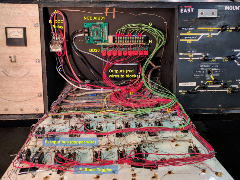
Note that here we have a mix of the original block toggle setup and the ones with the block detectors, so let’s explain the original setup first, then the modified one with the DCC block detectors.
Original setup:
- A- DCC power comes in from the purple/orange wire pair.
- B- Power goes through that DCC relay. This is a remnant of the old DC / DCC / DCM selection logic, which I simplified. I kept the DCC relay as it makes it easy to disconnect a panel to work on it.
- C- The output of the DCC relay are these thick black and red wires. Counter intuitively, these do not power this panel directly. That would be too easy. Instead they go to a terminal block hidden behind the mountain panel. The black wires from both Mountain Panels 1 and 2 are then bridged together (yet another remnant of the DC common rail design of this layout), and only the red wire comes back to this panel.
- D- The “input” red wire is lost into that thick bundle of red cables, and eventually connects to an unsheathed copper bus bar (E) that runs on the entire backplate of the panel.
- F- Individual toggle switches take power from that bus bar, and output power to a red wire, which then goes somewhere under the layout and connects eventually to the corresponding block. That’s the thick red wire bundle (D). These are the outputs of all the block toggle switches -- except for the similar-looking one that is the input to all of this.
There’s a reason we don’t design panels that way anymore, but let’s not dwell on that. It works good enough, and it has been for 5 decades or so. After all, this is located in a museum.
DCC block detection conversion:
- The red wire that is the “output” of a block toggle is unsoldered, and carefully removed from the bundle on the backplate of the panel.
- That wire is then slotted through a BD20 and connected to the terminal block.
- A green wire is connected to the other side of the terminal block and connected back to the original block toggle.
If we look at the electrical path in this setup:
- E- The “input” of the block toggles is still the unsheathed copper bus bar.
- G- The output of the toggle is the green wire, going to the terminal block.
- H- The terminal block output is the original red wire, going through the BD20 current detector.
It’s important to note that this way, the panel is basically unchanged in function. Block toggles are still operating as before. This was an explicit goal of this design, as it was initially requested to not change the existing behavior.
Aside from that constraint, the design is minimally intrusive and fairly simple to implement and comprehend. Keeping the block toggles in place has been somewhat beneficial as it allows to turn blocks off to work on them, or at least it does present the illusion one can do that (in practice, blocks were initially getting partial power from the coupling of the panels via the old Twin-T detectors bias resistors, before that was found out and removed).
19.1.4- DCC Block Detection on Other Panels
There are 3 other NCE AIU01 cards on the layout:
- One is visible by the Stockton Passenger Station. Due to a lack of space, this one only has 2 blocks detected. The goal was to add more later. This NCE AIU01 is also used for the motion detector that starts the automation. It used to have the initial automation mainline button for visitors, before that was removed..
- There is one under the mountain, near the hidden Branchline panel. It is used for detecting blocks on the Branchline. It used to have the initial automation branchline button for visitors, before that was removed.
- There’s another one under the Valley Panel 1. Currently it is only wired for the automation toggle buttons. The initial goal was to map the mainline blocks near the Stockton Station and in the return tunnel. However this panel is a complete spaghetti mess and it was deemed imprudent to apply the same design as used on the Mountain Panel. Alternatives are still being considered for this panel.
19.2- Turnouts conversion to DCC control
The goal of the automation is it must not change the behavior of the existing panels. We want to have some of the turnouts controllable via DCC accessory. Not all of them will be DCC controlled.
19.2.1- Existing turnout implementation
- The layout uses 3 kinds of turnouts: twin-coils, Fulgurex and Tortoise. It seems that twin-coils are used in the yards and the original mainline was apparently using Fulgurex turnouts. Later, some of the mainline and yard was changed to more modern Tortoises.
- Turnout panels use rotary switches for Tortoise and Fulgurex turnouts (mainline) and push-buttons for the twin-coils (all yards).
The rest of this focuses only on the conversion of the rotary toggles used on the mainline.
19.2.2- Existing wiring
- The existing turnout panels all use non-momentary rotary toggle switches.
- Power is provided by a regulated variable DC power supply located next to the DCC Command Station.
- It's not a flimsy power brick, it's a sturdy regulated power supply with 2 knobs to adjust voltage and amp current limit and 2 analog meters.
- The power supply has a label that says "11 V DC max" (measured 10.5 V at the panel).
- There is no indication of how much amps it gives. The analog meter shows 1 amp at rest so that must be the current set limit.
- Each rotary toggle switch is a 6PDT with only 2 poles used, so it ends up being the typical DPDT wired in a cross-over configuration. Turning the toggle effectively inverts the input polarity.
- Input is the DC turnout power (red wire is negative, white wire is positive).
- Inside the panel, all red wires are connected together using a terminal block where all terminals are connected together with a bare wire.
- Output of each DPDT is 2 wires, white and green. The whites ones travel directly to the corresponding turnout. The green ones are connected to another 1-to-1 terminal block inside the panel.
Schematics of the original wiring:

To provide DCC control, we're using NCE Switch-8 boards. These can control directly Tortoise turnouts.
Fulgurex turnouts cannot be used directly because the motor uses more amps than the Switch-8 can provide. To compensate, we'll be using NCE Relay Boards to control these via the Switch-8.
Twin-coils turnouts from the yards are not DCC controlled at this time.
One of the mandates is to keep manual control as-is. The Switch-8 controls the turnouts directly without being wired to the rotary toggle switches. It does accept an add-on card, the NCE Button Board, which connects to the toggles and sends commands to the Switch-8 to switch the turnouts.
19.2.3- DCC implementation details
- A second regulated variable power supply is used for the DCC turnouts. Same as the first one, I found we had 2 of these. This one is set to 12 V measured at the panel. We need a higher voltage since the Switch-8 drops one or two volts so this leaves the output roughly similar to the non-DCC controlled turnouts. I also set the amp knob to 1 amp like the first one.
- The NCE Switch-8 is powered by the second power supply: the red/yellow wires (look like a solid 12-14 AWG pair) goes to a terminal blocks and a shorter wire goes to the Switch-8 on its barrel power plug.
- An NCE Button Board is connected to the Switch-8 "Button Board" terminal block using 3 wires (green for data, black/red for power).
19.2.4- To convert a Turnout to DCC using NCE Switch-8
- First power off the layout at the mains.
- Disconnect the white and green wires (output) from the toggle 6PDT switch. Connect them to the Switch-8 via the corresponding terminal block.
- Since the original rotary switches are 6PDT and only 2 poles were used, select an unused pole and connect it as a 1PDT to the Button Board: striped-white-green wire from Gnd to common, and one wire to N (striped green) and one wire to R (solid green) on the input number matching the output number on the Switch-8.
- Check continuity of connexions.
- Power again the layout.
- Set the Switch-8 power to DCC and use a NCE ProCab to program the turnout DCC address. Then set the Switch-8 power back to DC.
- Check normal/reverse direction on the turnout. If incorrect, simply swap the white/green wires on the terminal block under the Switch-8.
Schematics of the DCC controlled turnout wiring:
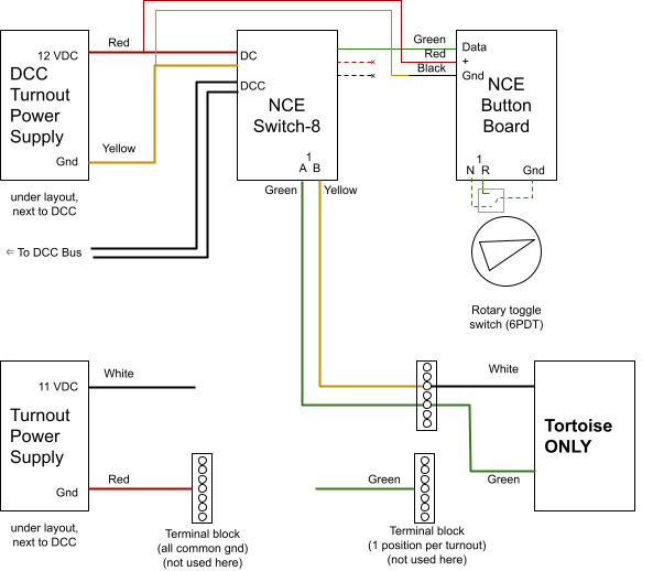
Notes:
- When powered, the NCE Button Board has a red light LED turned on. It momentarily turns off when a rotary toggle is turned.
- When powered, the NCE Switch-8 displays "1" then "1" then settles on a little 3-bar sign.
- When one of the rotary toggles is turned, the NCE Switch-8 displays an hexa number 0..F corresponding to the button board input triggered. 0/1 for turnout 1, up to E/F for turnout 8. The even numbers indicate Normal direction and odd numbers indicate Reverse direction.
19.2.5- Somewhat Correcting the NCE Button Board
The NCE Button Boards were chosen because their documentation clearly indicates they work with non-momentary contact (i.e. the rotary contact switches used at Randall). However the boards delivered by NCE have a “bug” in their firmware that makes them not work in this mode. When asked about this, NCE claimed the button boards do support only momentary contacts and that the documentation is wrong. The web site has been rectified to indicate the latter.
There are actually two issues with the NCE Button Boards:
- Their behavior is indeed incorrect when using non-momentary contacts.
- They work for a while till they don’t work anymore.
I wrote an extensive article on my site that explains the software issue when I was researching how to fix it and this chapter is a condensed version of that article: https://www.alfray.com/trains/nce_button_board.html
Overview
For DCC turnout control, NCE sells the NCE Switch-8 which decodes DCC turnout commands from the DCC power bus and controls up to 8 turnouts slow-motion machines such as Tortoise. This board does not offer anything to control the turnout from a fascia panel. For that, they sell the add-on NCE Button Board -- push buttons are connected to the Button Board, which in turn is connected to the Switch-8 using a serial port.
Wiring could not be any simpler, here is the Button Board on the left of the Switch-8:
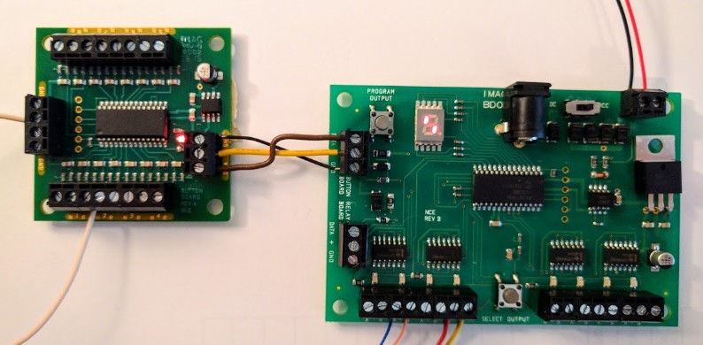
Just 3 wires need to be connected: data (a serial port), and +/GND for power.
The power comes from either the DC barrel plug or the DCC of the Switch-8, depending on the switch selector on the Switch-8 board. The DC is delivered almost as-is (it goes through a diode so there's a minor voltage drop) and the DCC goes through a full bridge rectifier first.
Issue 1: Lack of Non-Momentary Support
Train layouts typically use two kinds of toggles for turnouts:
- Push-buttons, typically two per turnout, one per direction (normal vs thrown). These are called “momentary” contacts as the contact is made only when a button is pushed.
- Rotary buttons with two positions. These are called “non-momentary” contacts as the contact is permanent for a direction once the rotary toggle is thrown in a certain direction.
The Randall layout uses push-buttons for twin-coils machines for the yards ladder selections, and uses non-momentary rotary toggles pretty much everywhere else, especially the mainline, for Fulgurex and Tortoise slow-motion machines.
The documentation provided with the board and available on the web site here still explicitly indicates it supports both types (see last sentence):
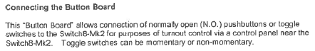
I based my selection of this NCE turnout control on that. It turns out that pretty much all other board manufacturers support only momentary contacts (push-buttons). However, upon inquiry, I was told later by NCE that the documentation was wrong and/or obsolete and non-momentary toggles were not supported. The zendesk help page clearly indicates it supports push-buttons and “toggle switches''. The definition of a toggle switch is a non-momentary switch (e.g. like a wall light switch) unless explicitly specified otherwise.
This is what led me to my research described in that article: http://www.alfray.com/trains/nce_button_board.html.
I determined that the easier way to fix the issue is by simply reprogramming the firmware on the NCE Button Board. From a software perspective, supporting both kinds of contacts is not exactly complicated. It also turns out that the hardware design of the NCE Button Board makes it trivial to update its firmware.
To reprogram it, we need a few things:
- The MPLAB X IDE.
- The MPLAB XC8 compiler.
- The MCC add-on for the MPLAB X.
- A PIC programmer such as the Microchip PICKit3.
- A Linux or Windows box.
Steps:
- Install the MPLAB X IDE, the MPLAB XC8 compiler, and the MCC add-on.
- Use git clone to download the source from https://github.com/model-railroad/conductor
- Open the ButtonBoard2.X project in MPLAB X.
- Make sure the NCE Button Board is *NOT* powered.
- Connect the PICKit3 to the Button Board as shown below. The "1" pin on the board must match the triangle pin on the programmer.
- In MPLAB X use the "Make and Program Device Main Project" button to compile the code and reflash the board.
- Disconnect the programmer.
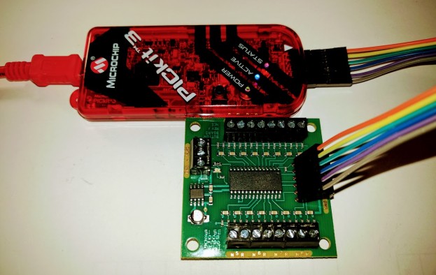
My implementation of the NCE Button Board firmware has an extra feature: when the board initializes (e.g. when first powered up), it cycles through the 8 turnouts and re-aligns then according to the position of the rotary toggles. This way when the layout is first powered in the morning, all the DCC turnouts are aligned according to the panels’ toggles positions. There’s also a 6-second timeout to let the Switch-8 board initialize before triggering the first turnout, and 1-second delay after each turnout command. This means the board needs 6+8=14 seconds to initialize.
Note that after contacting NCE, they also sent me a hex file to reflash the NCE Button Board using a new version of their firmware that would support non-momentary contacts. The one itemized above is my own, flashing the one from NCE is similar and turned out to yield similar results. To state the obvious, reflashing the board would void the warranty and should only be used by people familiar with these tools.
Issue 2: Unresponsiveness
In the mainline experimentation phase, I wired one NCE Switch-8 and one NCE Button Board. They seemed to work nicely but soon enough I found that rotating a toggle would do nothing. There is a 7-segment display on the Switch-8 which indicates when it receives a command and which turnout it is changing. Using the Button Board, it would work for a while then become unresponsive -- turning a rotary button would register on the button board (via its internal status LED) but it no longer made the Switch-8 change that turnout. However the Switch-8 would always reply to DCC turnout commands such as those issued using an NCE Pro Cab ACCY button.
The issue seems to be related to the serial port communication between the NCE Button Board and the NCE Switch-8. They both work individually, but become unresponsive “after a while”.
Experimentation showed that cutting power to the Switch-8 and restoring it would make the Button Board work again.
I identified that the Button Board seems to work much better when it is powered directly from the same power supply as the NCE Switch-8 instead of being powered via the NCE Switch-8. That is:
- Do not connect the + / GND from the NCE Button Board to the + / GND of the Switch-8.
- Instead connect it to the Red/Yellow wires of the DCC Turnout Power Supply.
Using a relay, I came up with a system that powers the Switch-8 first and then the Button Board. This seemed to improve the situation substantially.
None of these workarounds worked satisfactorily, and the unresponsiveness issue would always show up later. In the end I reverted the power to how it should be (power from the Button Board from the corresponding Switch-8 power terminal) and simply installed a cut-off switch on the Mountain Panel; it’s that red button in the middle at the top of the Mountain block panel:
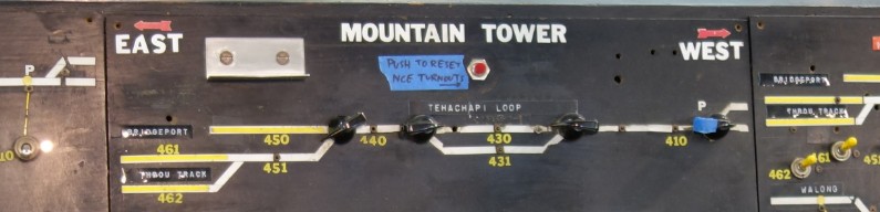
Pushing this red button simply cuts the power to the Switch-8. The downside is that when released the Button Board goes through its initialization sequence, which has indicated above takes between 6 to 14 seconds.
The plan in the original automation experimental phase was to also convert other panels (notably the Valley panel) to the Switch-8. Given the issues I encountered with this first conversion, I decided to postpone further conversions. The Saturday operators who mostly use the Valley panel and Stockton Yard panel have a very low tolerance for things that “mostly work” and a low acceptance level of things that differ from what they were used to.
19.2.6- To convert a Turnout to DCC using Digitrax DS64
TBD -- summary: ok for Tortoise, not for Fulgurex; need to expand this -- for now point to blog post with the details.
Blog post Experiment with using a Digitrax DS64 has more details on the DS64 and its specific details, here’s just a summary:
- The DS64 offers 4 outputs. It can drive either twin-coils or Tortoise turnouts, but not a mix.
- One output can trivially power a dual Tortoise (for a cross over).
Short-commings:
- Must be powered from the track for DCC commands to be intercepted. That’s an issue as we typically do not want to power a turnout controller from the same track that may be short-circuited if a train derails on a turnout.
- Workaround: Ensure the DS64 is powered from a different circuit breaker than the turnouts under control.
- The DS64 is not suitable for Fulgurex slow motion motors! These are output of spec. Depending on the actual motor power usage, it may work marginally. If the motor draws too much current, the voltage drops and the turnout won’t throw.
- Workaround: Trigger the fulgurex via a relay, as is done with an NCE Switch-8. Which negates the point of using a DS64 here in the first place.
- I programmed the DS64 to start in its last known position. In practice, I found sometimes the DS64 reverses some turnouts when powered on, even though they have not been used at all during the last session. To be fair this happens very very rarely (maybe twice a year) but it always surprises operators who do not check their turnouts before they run and as such is a bit of a nuisance.
- DS64 User Manual OpSw 6 is set to factory default (restore last state on power up). The other option is not powered till they receive a command. I could try that, although I like the idea of the motor being powered to apply pressure on the point.
- Possible workaround: when it is powered up, the DS64 uses the A/S inputs if set. So one option is to use that to force the turnouts to normal. And maybe that’s exactly the cause of the issue, as these are currently floating with nothing connected.
- Workaround: In JMRI or in Conductor, do the typical trick of forcing all turnouts state when the program starts. This must be a double pass where all turnouts are set to reverse then all set to normal, to ensure the NCE command station is in sync with the DS64 no matter what its state is.
19.2.7- Fulgurex Turnouts
The NCE Switch-8 cannot control the PFM Fulgurex turnouts directly.
There are two potential solutions:
- Add an extra NCE Relay Board to interface the Switch-8 to the Fulgurex.
- Use a Digitrax DS64 instead of the NCE Switch-8.
For now I experimented with the NCE Relay Board and got successful control of the Sonora turnout (T330).
The NCE Relay Board is wired as follows:
- The input of the relay board has a pair of 2-position terminals.
- When looking at the board with the input on the left, the top terminal of each pair is the - side of the relay and must be connected to the ground of the Switch-8.
- The bottom terminal of each pair is the + side of the relay and must be connected to the either A or B output of the Switch-8.
- Use the A output by default or use the B output if it needs to be inverted.
- Do not connect both inputs of the relay board to both A and B at the same time. This is what the NCE documentation says to do but it's actually fairly useless from an electronics point of view as it means the relay diodes will unnecessarily always be in reverse voltage when the relay is in its normal position.
- The output of the relay board has a pair of 3-position terminals.
- When looking at the board with the output on the right, the bottom of each terminal is the NC (normally closed) position and the middle one is the power supply.
- To wire it to be normally thrown by default, we want to match the middle and the bottom one.
- The positive side of the power supply goes to the upper terminal and the white wire goes to the bottom position of that same terminal.
- The ground side of the power supply goes to the lower terminal and the green output wire goes to the bottom position of that same terminal.
If it is wired this way, the relay will have the Fulgurex match the normal/thrown direction of the Switch-8.
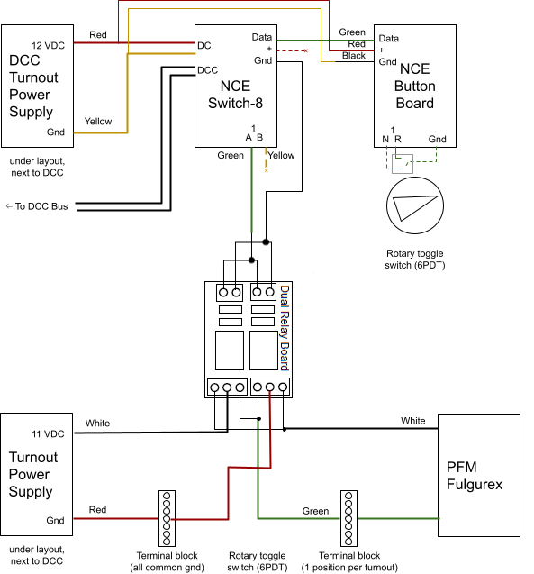
19.2.8-Twin-Coil Turnouts
The NCE Switch-8 cannot control twin-coil turnouts directly. These are mostly used in the yards, typically all the yard ladders with their matrix route controls.
There are two twin-coils used on the mainline to come in and out of Fairfield at blocks B130 and B110. They are both non-functional.
There are potential solutions:
- Using an NCE Q-Snap to control up to 4 twin-coils. I’ve used that product and it generally works but can have issues driving dual-turnouts in a crossover configuration using a single output.
- Use a Digitrax DS64 instead of the NCE Switch-8, as it can be configured for either twin-coils or slow-motion machines (but not for a mix on the same DS64).
- Using an Arduino and SSR relays as per my example here: https://www.alfray.com/trains/arduino_turnouts.html.
Note that these SSR relays require the use of an AC power for the twin-coil, which is the type being used at Randall. - Replace them by Tortoise slow-motion machines and then reconsider the DCC control as explained two chapters above.
19.3- List of DCC Controlled Turnouts
This is an exhaustive list of all currently DCC-controlled turnouts:
From Mountain Turnout Panel:
- T311 -- Switch-8 #1 to Tortoise
- T320 -- Switch-8 #1 to Tortoise -- disconnected
- T321 -- Switch-8 #1 to Tortoise
- T322 -- Switch-8 #1 to Tortoise
- T324 -- Switch-8 #1 to Tortoise
- T326 -- Switch-8 #1 to Tortoise
- T330 -- Switch-8 #1 to NCE Relay to Fulgurex
- T504 -- Switch-8 #1 to Tortoise
- T450 -- Switch-8 #2 to NCE Relay to Fulgurex
From Valley Turnout Panel:
- T140 -- DS64 #1 to Tortoise (Sultan)
- T150 -- DS64 #1 to dual Tortoise (Mainline to Sultan)
- T151 -- DS64 #1 to dual Fulgurex (Mainline to Napa)
- T160 -- DS64 #1 to dual Fulgurex (Napa to Richmond)
(last updated 2020-12-12)
19.4- Automation Toggles
One of the principles elaborated early on is that the automation does not prevent “operators” from running. Operators are volunteers who typically join on Saturdays to run their own trains. They need a simple mean to prevent the automated trains from running on the mainline while their trains are running, especially on the Mountain area which is single-track.
Another need is for the museum staff to stop the trains from running before turning off power daily.
19.4.1- Single Automation Toggle (2017)
While implementing the experimental and the MVP phases of the mainline automation, I had allocated a single automation toggle. This consisted of a single two-position toggle (on/off) mounted on the Passenger Station Panel. The toggle closes a contact and is detected by the NCE AIU01 module from the Passenger Station.
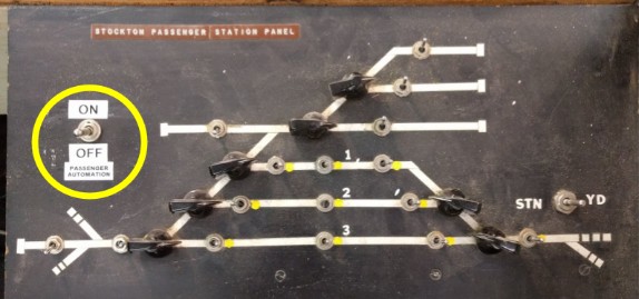
In the automation program, the automation toggle had the following effect:
- When off, it would prevent activation of the trains by the Automation Trigger (see below).
- While turned off while an automated train was running, it would stop the train and return it back to the station.
The automation was programmed in a safe-fail mode: it would only start if trains were at their expected starting position. If power were to be turned off while the trains were anywhere else on the track, the automation has no record of which train is where and cannot properly initialize.
The Automation Toggle thus acted as a cut-off switch. The idea was that the museum staff, when closing at 5 PM, would fist turn the toggle off. This would prevent trains from departing. It would signal to any running train to come back to the station. The staff personnel would then wait for the train to be idle at the station, and then and only then power could be turned off. Unfortunately, due to a combination of neglect, apathy, and miscommunication, this failed more than few times, requiring manual intervention to re-align the trains before starting the automation again.
Another issue was the location of the toggle on the Passenger Station panel. This was fine during 2017 as the panel was readily accessible and the location was chosen as it was located where we were actively working on the layout. However in December 2017 the museum erected a glass barrier around the layout, which essentially prevented easy access to the Mountain and Passenger Station panels as it required to open a locked door first. The combination of the locked access, and the location not being near the DCC main power off switch gave even less incentive for staff to properly use the toggle as originally intended.
This automation toggle has been removed from the Stockton Passenger panel in 2020. (actually still there, update this once removed)
19.4.2- Dual Automation Toggle (2018)
In 2018, I introduced a second automation toggle to be able to run the Branchline and the Mainline automation independently. This was useful for Saturday operators: since they run on the Mainline, they need to turn off that automation. However the Branchline automation can stay turned on, and it provides more variety for the public.
The additional toggle consisted of a single two-position toggle (on/off) mounted on the Mountain Panel. The toggle closes a contact and is detected by the NCE AIU01 module from the Mountain Panel. In the automation program, it would be used to enable the trigger of the Branchline automation.
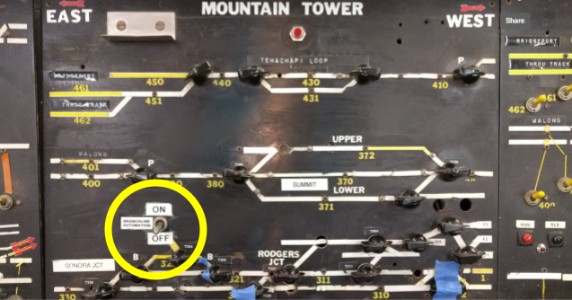
On the automation program side, the fact of turning off the toggles during a train run was modified to not always stop a train and bring it back. Instead that was changed on a per-block basis as some trains responded negatively to having their direction changed on certain parts of the track.
Finally the shutdown procedure for the museum staff was changed to not make turning off the automation toggles mandatory as long as they ensured that trains were back at their main station before turning off power.
19.4.3- Update to Automation Toggle (Mid 2018)
In mid 2018, while still keeping two toggles (one for Branchline, one for Mainline automation), I moved them to the Valley Panel. This made them more accessible by being located closer to the DCC power switch used by the museum staff and also more accessible to the Saturday operators.
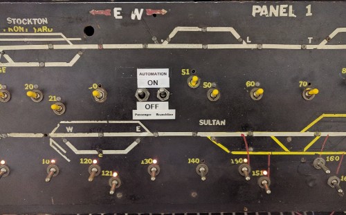
As indicated above, one issue was with the staff sometimes not checking the trains position before turning off power. After discussion with the museum staff, I suggested to automate this behavior. Since the museum closes at 5 PM, the staff want people to start leaving shortly before that time, but it’s hard to get some visitors away when the trains are still running. A simple program change was to programmatically turn off the JMRI sensor variables at 4:50 PM -- effectively that means the toggles are still physically “on” (and will be read as such by JMRI the next time the computer boots) yet from JMRI’s point of view they are logically “off”. This leaves 5 minutes for whichever train is running to finish its cycle before the staff comes by to turn off power.
19.5- Automation Trigger
The automation is on from roughly 10 AM up to 5 PM. We want the trains to run automatically only when visitors are present (to minimize wear and tear, etc). Initially, the intent was for the train automation to start “by the push of a button”. This provided an obvious level of interaction between visitors and the automation.
Note: “Automation Trigger” is not to be confused with “Automation Toggles” (See 15.3- Automation Toggles):
- “Automation Toggles” are on/off switches for staff & operators to disable the automation.
- “Automation Trigger” is what triggers the departure of the trains and starts their automated run cycle.
19.5.1- Activation Buttons (2017)
The initial automation had two routes, branchline and mainline. Consequently two activation buttons were provided, one for each line, located on the fascia roughly where the trains are stopped when idle.
As I had initially selected NCE AIU01 modules to connect the block detectors, this also provided a convenient and logical interface to connect activation buttons. The NCE AIU01 inputs are active high (5V), with an internal 10 kΩ pull-up. They are designed such that closing a simple contact would trigger the input.
Each button is seen as a JMRI sensor that is either open or closed. This keeps the implementation simple and the programming straightforward as the button inputs are handled as any other sensor event.
As far as automation programming is concerned, the activations buttons are only checked when the trains are idle. Concerns were emitted by other parties whether continous activation of the buttons could result in incorrect automation state. However that concern was not founded as it all depends on the programming: once trains start their run, the state of the buttons is not used by the automation program to start the trains.
In an early experiment, we tried using the buttons when a train is running to activate the trains horns. This is trivial from the automation program perspective. However we quickly found out it resulted in the horn getting “stuck” (continuously activated). This happened a lot in the mountain area of the layout, where we were also having difficulties with specific engines (not the ones used in the automation though). We also had operators before complain their trains run slower in this area, in which the wiring is known to have issues (see 4.1- Wiring) This likely had to do with the DCC horn-off command being missed by the train, which can happen as it is not repeated. Rather that identify and fix the issue, it was suggested to simply drop the feature.
In any case, the initial implementation was simple.
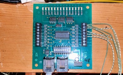

The Branchline activation button was connected as an input on the Brancheline NCE AIU01:
AIU01 address 48 for the Branchline sensors:
Bit |
JMRI |
Description |
Bit |
JMRI |
Description |
1 |
752 |
BL Block Parked |
8 |
759 |
-- |
2 |
753 |
BL Block Station |
9 |
760 |
-- |
3 |
754 |
BL Block Tunnel |
10 |
761 |
-- |
4 |
755 |
BL Block Reverse |
11 |
762 |
-- |
5 |
756 |
BL Block Reverse 2 |
12 |
763 |
-- |
6 |
757 |
-- |
13 |
764 |
-- |
7 |
758 |
-- |
14 |
765 |
BL Activation Switch |
And the Mainline activation button was connected as an input on the Passenger Station NCE AIU01 with the idea of expanding this with a second button later for a second mainline train:
AIU01 address 50 for the Passenger Station Panel: (2018-01)
Bit |
JMRI |
Description |
Bit |
JMRI |
Description |
1 |
784 |
PA Toggle Switch |
8 |
791 |
B502a |
2 |
785 |
PA Activation Switch |
9 |
792 |
B502b |
3 |
786 |
B503a |
10 |
792 |
B502c |
4 |
787 |
B503b |
11 |
793 |
B501a |
5 |
788 |
B503c |
12 |
794 |
B501b |
6 |
789 |
B504 |
13 |
795 |
B501c |
7 |
790 |
PA Activation Switch 2 (future) |
14 |
796 |
-- |
Note: “PA Toggle Switch” is the Automation Toggle described in 15.3.1- Single Automation Toggle (2017).
19.5.2- Activation Buttons, Missed Events (2018)
Very quickly we noticed that sometimes the system would fail to notice the button was pressed.
We use a large button but that’s irrelevant. The issue has to do with how long it is pressed. Most people give a quick short push, and that’s the problem.
The button directly closes the contacts on the NCE AIU01, which is regularly polled by the NCE command station. The computer runs my Conductor software which polls JMRI for the status at at least 30 Hz. However the AIU01 is polled by the NCE Command Station at an appalling low refresh rate due to the NCE cab bus implementation: if an input doesn't trigger long enough (e.g. 1 second), it will be easily missed. In this case, it’s enough to give a short but quick push to the button and most of the time miss the polling window. The event is simply missed.
Question is what would be the simplest circuitry possible to make an input trigger longer?
From the NCE AIU pdf:

There's a grounded common and a 5V pull up on each input.
- When the input is open, the Microchip input is pulled up and the inverter sets the other side of the LED to low.
- When the input is grounded, the Microchip input is pulled low, protected by the 10k resistor and the inverter sets the other side of the LED to high, thus lighting it.
The obvious way is to use an NE555 to generate e.g. a 1-second pulse. It can be powered by the 5V from the NCE AIU to make sure they share the same ground and power (both 5V need to match to be a closed circuit). This requires at least one RC circuit on the 555, and we need one per input to deal with. If we wanted to “convert” all 14-inputs, since an NCE AIU has 14 inputs, even using a 558 (a quad 555) would still require 4 chips and some wiring or a PCB. And here I have a single button to deal with, so it seems like a lot of extra work for a single input.
At the other extreme, the “simplest” circuit would be to not have any extra circuitry at all. One option I do not have is reprogram the NCE AIU01 -- first because this board does not have the PIC16F's ICSP (In-Circuit Serial Programming) exposed like the NCE Button Board did, and second I don't think NCE would give me the source, which is too bad because I could just trivially do the 1-second delay in software -- or more exactly, sample and latch any trigger input till the next read from the NCE bus, and third as I explained above (see 14.4- Automation Philosophy) I want to avoid customizing these off-the-shelf components unless I really have no other choice.
A more "modern" solution would be to stick an Arduino in between, e.g. an Arduino Nano is fairly cheap. How many would I need for 14 inputs? 18 pins usable per Nano e.g. 9 inputs and 9 outputs. The Nano can be powered from the 5V from the NCE AIU and would basically simulate the inputs for the AIU. Although at that point, I’d basically add an RS485 shield to the Arduino and consider getting rid of the NCE AIU to begin with.
Enough brainstorming. The cheapest and simpler solution (as in "less wiring") would be to put a capacitor on the input, it should lower it slowy and then raise it slowly. That would introduce a delay into the trigger and the release so it might be good enough. The time constant to reach 63% is τ = R x C. Say the capacitor is fully discharged. We have R=10 kΩ, τ=1s ⇒ C=100 µF and τ=0.5s ⇒ C=50 µF. That's not unreasonable. There should be some resistance in series with the button to not fully short the capacitor say something like 100 Ω or 1 kΩ.
And I tried just this, using R=110 Ω and C=1000 µF because that’s what I had around. A full long button press activates the signal for a good 5-7 seconds after release. Even a very short button press still activates the signal for a couple seconds.
The one consequence is that when powering the DCC, the signal is activated as the capacitor charges for also the same amount of time. This is not a problem since I have a full laptop with JMRI that needs to boot and it takes way longer than the initial charge time.
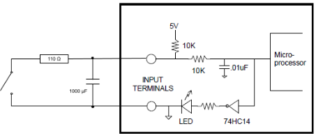
This is the solution I used. On both the AIU modules for the Branchline and the Passenger Station, I soldered a 110 Ω in serie with the button and placed a 1000 µF capcitor between the input and the ground. This solved all the missed button pushes.
19.5.3- Motion Sensor (Mid 2018)
In 2018 we changed the automation trigger from a visitor-pushed button to a motion sensor. This reduces the nuisance due to people hammering buttons needlessly. It also allows the automation to work as soon as someone enters the viewing area with no need to understand and perform any action.
On the blog, [2018-09-15] NCE AIU01 and Motion Sensor discusses the process used to design this motion sensor-based activation. Here we will focus on the end result and the troubleshooting steps.
The motion trigger is composed of two main hardware components:
- One PIR arduino sensor HC-SR501
- (source: 1 pack of 5 for $10ish: https://amzn.to/2IB9P20 or similar)
- A modified NCE AIU01 board to connect the PIR sensor. This board also monitors the trains when they are are stopped at the Stockton Train Station.
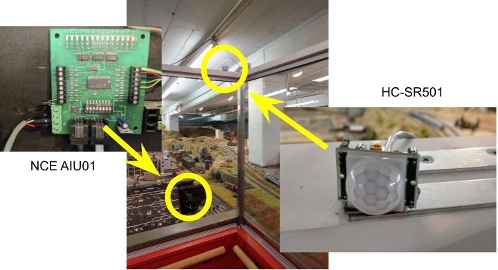
On the software side, the following happens:
- The NCE AIU01 pools the sensor.
- The Conductor software, running on the automation computer, uses that information to trigger train automation.
- The automation computer broadcasts the motion status over the railroad’s private wifi network.
- The tablets display the motion status relayed by the computer.
Maintenance wise, the following parts could fail:
- The HC-SR501 sensor could fail, or it’s connection to the NCE AU01 board could become loose.
- Troubleshooting: A red LED turns on on the NCE AIU01 board when motion is detected. A simple test is to stand in front and expect a LED on the board to turn on. See below for details.
- The NCE Command Station or the interface with the computer could fail.
- Troubleshooting: Does the automation computer properly display its map and does the map properly register the presence of the automated Passenger train stopped at the station? If it does, then that part works as expected and the NCE AIU01 status will be properly handled.
- The tablets could be out of sync with the automation computer.
- Troubleshooting: Does the tablet reflect the proper state for the automation on/off switches? That’s easily verified by toggling them on the Valley panel and verifying the corresponding display changes on the tablets.
Here’s the schematics of how the HC-SR501 is connected to the NCE AIU01:
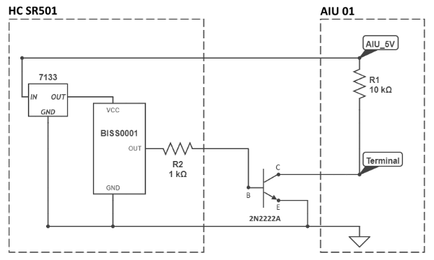
Wiring and detail of the HC-SR501 PIR arduino sensor:
- Connect the 3-pin output to the provided cable, with the following pin-out:
- Black = GND
- Green = High/low output (3V).
- Red = Power (5V).
- Jumper must be moved to the “(L) Single Trigger” position.
- Sensitivity is adjusted to (TBD… confirm, I believe mid-range was good).
- Time-delay is adjusted to (TBD… confirm, I believe mid-range was good).
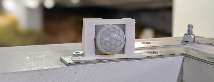
Currently the sensitivity is such that a small child located in front of the automated trains when parked at the station should be detected. Adults are detected much farther away. Time detail should be adjusted to pulse the output for at least one second otherwise the NCE AIU01 may not pick it up. A pulse output of something like 3~5 seconds seems ideal.
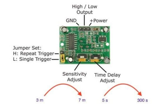
(image source: the internet)
Source: it’s easy to procure a replacement if needed. There are tons of these on eBay/Amazon. Here’s an example for reference: 1 pack of 5 for $10ish, https://amzn.to/2IB9P20.
Detail on the modified NCE AIU01 board:
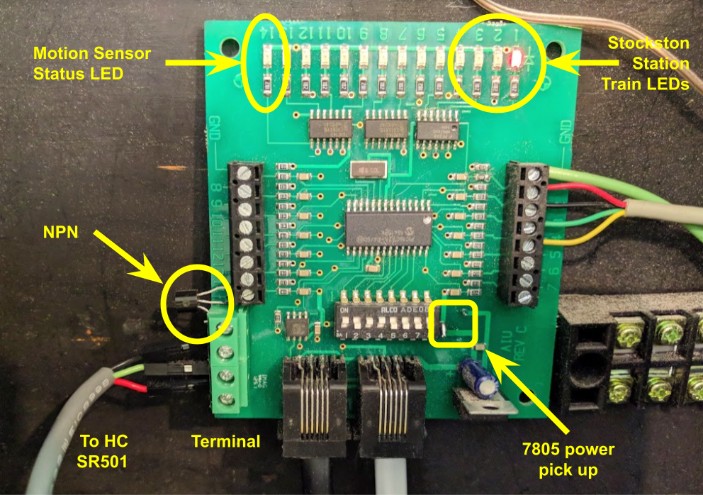
Details about the NCE AIU01 board:
- A 4-position terminal has been added to the bottom left corner.
- The terminal has the follow position, from top to button:
- #1 Top is the output of the HC-SR501 sensor (green connecting wire).
- #2 Middle-Top is ground, connected to the ground of the 7805 on the board (black wire).
- #3 Middle-Bottom is the output of the HC-SR501 sensor (green connecting wire). It is bridged to position #1.
- #4 Bottom is the positive, connected to the +5V of the 7805 on the board (red wire).
- An NPN 2N2222A transistor is connected per the schematic above: Emitter to ground, Base to the terminal position #1/#3, and Collector to input pin 14 on the NCE AIU01.
This is not an off-the-shelf module anymore, yet not a strong deviation from it. The NCE AIU01 is an off-the-shelf component, and the modifications I made to it are trivial enough (and documented here) that a replica could be easily made if this one came to stop working.
With this change, the mapping of the NCE AIU01 for the Passenger Station is as follows:
AIU01 address 50 for the Passenger Station Panel: (2018-09)
Bit |
JMRI |
Description |
Bit |
JMRI |
Description |
1 |
784 |
Unused |
8 |
791 |
-- |
2 |
785 |
Unused |
9 |
792 |
-- |
3 |
786 |
B503a |
10 |
792 |
-- |
4 |
787 |
B503b |
11 |
793 |
-- |
5 |
788 |
-- |
12 |
794 |
-- |
6 |
789 |
-- |
13 |
795 |
-- |
7 |
790 |
-- |
14 |
796 |
Motion Sensor |
To diagnose that the PIR sensor is working, it’s as simple as standing in and out of front of it and validating that the corresponding light #14 turns on on the NCE AIU01 board.
19.6- Computers & Infrastructure
This section describes the computers and associated network infrastructure used for the “train exhibit”.
As a design rule, none of the computers should be required to run trains manually. This is all done via the NCE Command Station and the DCC Power Boosters. Even the remotely controlled turnouts are controlled by the NCE Command Station.
One computer, namely the “automation computer”, is required to run the automation. The other ones are either backup or accessory support systems.
19.6.1- Networking
The train room offers two wifi networks:
- A “semi-public” wifi SSID is offered for the volunteers. That’s because we have basically zero cell phone coverage in the room, and the main museum wifi is mostly too weak to be properly usable. This wifi is provided by an RE6300 reconfigured as an AP and connected to the wired ethernet located next to the power panel, by the entrance of the room.
- A “private” wifi SSID, isolated and only used by the train room automation.
Two range extenders are located in the train room:
- Linksys RE6300 (https://amzn.to/3gvTuOL) by the front door belongs to the museum. Connects to the museum wifi and rebroadcasts it in 2.4 Ghz and 5 GHz, with the limitations explained below. That’s the one that provides the “semi-public” wifi network for the volunteers, in AP mode.
- TP-Link AC750 (https://amzn.to/3wnMXwr) for the rear room belongs to Jim. The box is connected to a layout outlet below the entrance of Bridgeport yard. It connects to the front Linksys repeater and rebroadcasts it in 2.4 Ghz and 5 GHz. This is also available to the volunteers. This allows us to have some kind of wifi in the rear room, which is generally too far off from the museum wifi to get anything at all.
The train room has its own dedicated networking:
- A wifi router and a network switch provide wired connection between the various computers.
- The wifi router also provides a dedicated private wifi network.
The train WiFi network is isolated from the museum’s wifi. The train room is located in the museum basement with thick one-foot walls, and consequently access to the museum wifi is tenuous and unreliable. The connection to the museum wifi is at -80 dB, which is rather poor. When the train room has a sizable number of visitors, the connection totally drops.
Due to its inherently weak setup, the museum wifi should be treated as an unsecure DMZ. Consequently none of the automation computers should connect directly to that wifi.
Instead, the train wifi router provides a private wifi network. A connection between the train private wifi network and the museum wifi is done via a one-way net masquerading setup. This allows the train computers to have some form of outgoing internet connection when desired -- at least when the museum wifi is reliable enough.
A Raspberry Pi is located under the Mountain Panel. This one belongs to Raphael. It has a special performance external USB wifi antenna to have a better connection to the museum wifi. The RPi also performs the net masquerading to allow access to the museum wifi from the private train wifi. The RPi monitors the available wifi networks and connects to the best one it can find that actually provides an internet connection.
Power configuration: The wifi router, the RPi, and the network switches are connected to a specific outlet from the back room that should remain on 24/7 all the time. These must not be switched off with the rest of the layout power.
Historically, the RPi connected to the weak museum wifi, thus the need for a special boosted antenna. This was still rather inadequate since the connection was strenuous at best. Eventually an ethernet cable was pulled through the room to provide coverage for the theater above, and that gave us a wired access point. That’s when the RE6300 was reconfigured as an AP and connected to that wired ethernet connection. That brings a solid network connection and broadcasts it inside the heavily concrete-shielded train room.
The RPi now uses this local wifi network as its outgoing link, bypassing the weak museum wifi. However if the wired network is interrupted, the RPi fallbacks to the weak museum wifi. This has happened.
We also still need a repeater to reach the back room, because no signal goes by these thick one-foot walls.
19.6.2- Tablets
Tablets:
- tablet-1 -- Mountain / Entrance
- tablet-2 -- Valley
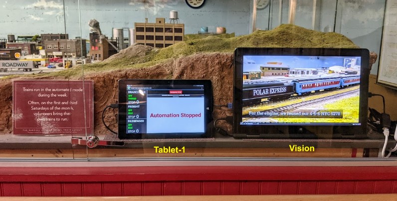
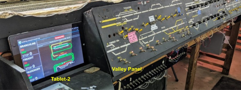
Specs:
- 10 inch Tablet Chuwi Hi10 Pro (http://amzn.to/2eCmEJY)
- Android.
- Runs the RTAC software.
Both tablets are configured to automatically run RTAC in full screen as soon as they boot.
They are configured to automatically connect to the “consist” computer over wifi.
Power configuration:
- Tablet-1 is powered via the Vision computer.
- Tablet-2 is powered via a USB power supply.
Normally, these tablets are “always on”. The RTAC software has some special logic to keep the tablets on when the “consist” computer is detected -- the screen is always on and the display nor the tablet never goes to sleep. However as soon as the computer connection is broken (when the layout is shut down), the tablet turns off the screen after a few minutes to save on power and eventually goes into sleep mode. It automatically wakes up when the connection is restored. That means the Museum Staff & Operators do not have to touch the tablets under normal usage. They are powered when the layout is turned on, and they sleep on their internal batteries when the layout is off (at night or week-ends).
However if the layout needs to be shut down for an extended period of time (weeks, months), it is recommended to physically turn off each tablet using the power button and then to turn them on when normal operating hours happen again. That will prevent the battery from getting exhausted. The power button is a silver button on the top left of the tablet. Booting up the tablets manually can be a bit tricky -- press the power button for about 10 seconds then do not touch the screen as the bootloader shows up to select between Android or Windows boot mode with a count-down, which is then followed by the Android bootloader, and eventually the RTAC software should start automatically once Android has finished booting. Then after a few seconds, the custom software will automatically try to connect to the automation computer if it is on and the wifi is working.
19.6.3- “Consist” Computer
This computer is the main “automation computer”.
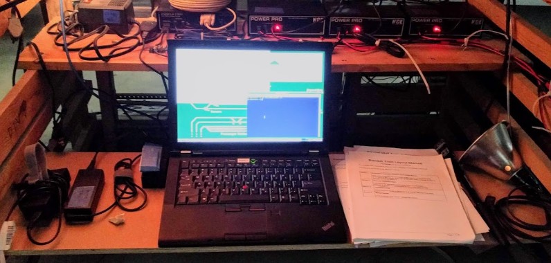
Specs:
- Refurb Lenovo Thinkpad T410.
- Debian Linux.
- Machine name: “consist”.
- Runs the Conductor software.
For this project, I chose to run the JMRI software under Linux on inexpensive laptop computers as I’ve done many times before.
Laptops are very convenient since they combine a battery, screen, keyboard, and USB ports all in a compact form factor that is easy to place somewhere on the layout out of the public sight. My selected choice is to use refurbished 4- or 5-year old laptops, and at the time of this selection, I liked to standardize on Lenovo Thinkpad T410/420; these units are commodities easily found on eBay or Amazon for very reasonable prices; they offer adequate levels of performance.
Maintenance wise, these laptops must be considered as shells -- if the unit dies, it just needs to be replaced by a similar model and the only work needed is to move the hard drive from the old to the new one. Linux makes it trivial to mirror the drive and have a copy of it, in case the drive dies.
Not all laptops are designed to be "repaired" (some are really hard to open); the older Lenovo Thinkpads are sturdy, easy to replace, well designed for this application, and readily available at attractive prices.
On the laptop, we run JMRI, an open source software designed to do train & layout control. It's used by a large number of clubs for tasks ranging from signaling to managing fleets and operating sessions, although here none of these features are being used. It integrates very well with the NCE command station, sensors and its accessories. JMRI does not provide a complete automation package by itself; it is however designed to be extended and I wrote custom extensions specific to the automation we desire to achieve.
The core software for the automation is named Conductor and is stored on an open-source public git repository:
https://github.com/model-railroad/conductor
The actual scripts and configuration used for the automation are all backed up on a separate private git repository. This is designed to make it possible to rebuild this computer and its configuration by having a copy of all the configuration files not on the premises, yet securely backed up.
Power configuration:
- The consist laptop is configured to automatically turn on when power is turned on using the DCC Switch.
- When power is turned off, the laptop will automatically shut down exactly one minute after power loss.
Museum Staff & Operators should not have to interact with the computer to turn it on or off.
Once the laptop boots, it automatically starts the Conductor software. The staff should not have to, and in fact must not, interact with the screen.
Exceptions:
- Very rarely the computer fails to boot with a BIOS TPM error. That seems to be about maybe once a year at most. In that case the staff needs to press the power button for 10 seconds to turn the machine off, then push it again briefly to turn it on.
- The one-minute shutdown delay means that if the DCC Switch power is toggled off/on for less than one minute, the laptop will start shutting down but it will miss its wake up event. It is imperative that the staff waits for the computer to finish shutting down or booting up before switching the power again.
19.6.4- “Decoder” Computer
This computer is located on the workbench in the rear room. It’s main function is to be a functional replacement for the “consist” automation computer in case the former one fails. It’s secondary function is to use JMRI on the programming track to set up DCC decoders.
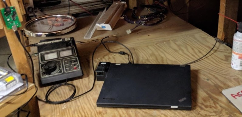
Specs:
- Refurb Lenovo Thinkpad T420.
- Debian Linux.
- Machine name: “decoder”.
Power configuration: since this computer is currently only a backup and seldom used, it does not have any special power setting. Just use the power button to turn it on, and then remember to turn it off once done with it.
This computer interfaces JMRI with NCE PowerCab using an NCE USB Interface.
Note in JMRI, configure connection using:
- System manufacturer = NCE
- System connection = NCE USB
- Port = /dev/ttyUSB[01]
- USB version = V7.x.x
- System: PowerCab.
- Default speed of 9600 on the USB card (JP1 off) seems to work fine.
- All jumpers off on the NCE USB board.
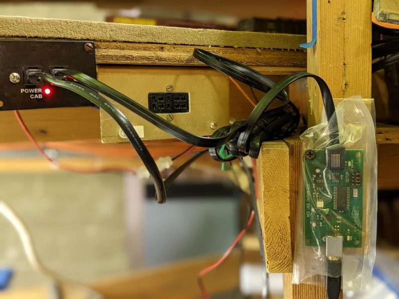
19.6.5- “Vision” Computer
The “vision” computer is located by the entrance and plays a continuous loop of videos recorded on this layout.
Alternatively it displays live train action from cameras located on the layout.

Specs:
- Refurb Lenovo Thinkpad Yoga 15.
- Debian Linux.
- Machine name: “vision”.
- Runs the Vision software.
Power configuration:
- The laptop is designed to turn on automatically when the layout power is turned on at the “North South” switch.
- The laptop is designed to automatically turn off 20 seconds after a power loss.
- When shutting down, it records a BIOS Wake Up RTC request for 5 minutes later. Concretely that means that once shut down, it will not turn on sooner than 5 minutes later.
Update 2022: this setup was unreliable and has been changed. Unlike the more robust Lenovo T series, this consumer-grade laptop does not always wake up when the power is turned on. Instead, the laptop is now powered 24/7. It monitors the Conductor laptop and the screen display is automatically turned on only when the automation computer is on with the rest of the layout. Otherwise the laptop seems “off” but it’s not really off.
Update 2023: The display now sometimes blink with some psychedelic patterns for a minute or two when the screen is turned on. This has all the marks of a display controller dying slowly, unfortunately. The laptop keyboard also developed issues (phantom keypresses) and I disconnected it inside the laptop. Despite all these problems, the laptop is powerful and the screen is just gorgeous and extremely adequate for this display task. Thus I plan to make it last as long as possible.
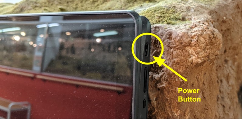
The Museum Staff / Operators should not have to interact with this laptop.
In the rare case that the laptop needs to be manually turned on, the power button is located in the top right corner. It can be a bit hard to see. Press it briefly and the laptop will turn on a few seconds later.
Once the laptop boots, it automatically starts the Vision software. The staff should not have to, and in fact must not, interact with the screen.
20- Mainline Automation
20.1- Initial Plan (2016)
The proposed initial automation plan is to have a passenger train leaving from the Stockton Passenger station, go up the mountain via the tunnels, up to Summit. There it would stop for a while on a siding and then reverse direction, going back down the mountain to the passenger station.
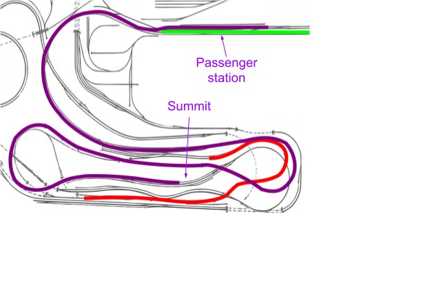
The suggestion is to implement this in 2 phases:
- Phase 1: bare minimum to get this running.
- 5 turnouts to control: 3 to exit Stockton station, 1 for Sonora, 1 at the Summit.
- 2 block detectors: one at the station, one at Summit.
- Phase 2: "ideal" reasonable number of turnouts controls and block detectors to cover the whole mainline in between both points.
The train used would be an Amtrak Superliner Coach with 2 engines, thus operating in "push pull" configuration. This way when the train comes back down the mountain, there will still be an engine in the front. The front and back engines should be as similar as possible (same model from the same manufacturer) to make sure they are perfectly speed matched. This is required to prevent the train from derailing when going in the reverse direction.
The benefit of splitting the work in the 2 phases is that we can, before opening, only deal with the first phase and make sure everything is ready for the opening day. Implementation of phase 2 can be done if there's leftover time or can be an ongoing operation done during maintenance days.
Hardware needed:
- In Phase 1: 6 turnouts to control: 3 to exit Stockton station, 1 for Sonora, 2 at the Summit.
- In Phase 2: 5 turnouts to control on the mainline, including the one already controlled by the branchline project.
- In Phase 1: 4 block detectors, 2 in the station and 2 at the summit to stop the train.
- In Phase 2: 5 detectors for each block on the mainline.
- One kid-friendly button needs to be mounted on a facade, probably close to the front.
- One master switch (to turn the automation on/off) needs to be mounted on the mountain panel
- Two NCE Switch-It 8 to control the turnouts. Each card controls 8 turnouts and is actually shared with the other projects.
- Two NCE AIU (auxiliary input unit) to report sensors and button states to the computer (we have 13 blocks and 2 buttons and each AIU has 14 bits). One of the AIU is shared with the branchline project.
At the minimum, we need to automate the turnouts to get from the station to the mainline and then the one at the summit to enter the siding. However there are numerous turnouts in between. A manual operator could have left these in any unknown position, making the train derail or go in another unexpected area of the layout. To prevent this, the only viable solution is to make sure all the turnouts between both points can be controlled -- when the automation start, they would be set in the desired route for the automation, thus preventing any unpredictable results.
This is the reason why the parts list in section 1 splits the hardware needed in phase 1 and phase 2: Phase 1 is the minimum hardware we need to make the project operate, and phase 2 is the extra one we need to guarantee the level of operation.
Each train requires having the last car modified to be detected by the block detectors, which is a simple modification that involves placing a resistor between wheels. This would ensure that the end of the train could be detected in case of uncoupling.
Time wise, the plan is to implement phase 1 modifications before the museum reopens to have something functional and then later update the layout with the modifications from phase 2 as we go along and if the automation is deemed satisfactory.
Visible automation:
- Train is stopped on the siding at the Stockton Passenger Station.
- Automation starts when the kid-friendly button is pressed.
- Turnouts align and the train goes behind the mountain panels, next to the branchline, on the bridge in the canyon, in the tunnel, up the mountain and turns back at the top and stops in a siding at the Summit.
- After a short pause, the train goes back in reverse using the same route back to the passenger station.
- Once the train reaches the station, it stops again and sits idle for 5 minutes.
- Pressing the button when the train is moving or less than 5 minutes after arriving at the station does nothing.
Automation off:
- A toggle switch should be added on the mountain panel to turn the automation off.
- When the automation is turned off, the train goes back to the passenger station if it wasn't there yet.
- Once that is done, the mainline turnouts are realigned and the train is stopped.
- Any press of the kid-friendly button is ignored when the automation is stopped.
20.2- Phase Exploration (2017)
Phase 0 is an exploratory phase which has been concluded.
Block detection:
- An NCE AIU01 card was installed next to the Passenger panel, with a 50-ft cab bus connected to the UTP panel next to the DCC command station.
- A single BD20 block detector was installed on the passenger station to make sure it behaved as expected. It proved easy to wire and worked right away, not needing any adjustment.
- It was expected that the BD20 would require tweaking (as indicated in the documentation).
- Since it worked, a second one was installed (2 were needed for the passenger station) as well as 2 more for the summit (where the passenger train reverses). They all worked on the first try using a single pass of the wire through the detector. No loop nor any resistor was needed.
- One issue was found later with block B370: the BD20 detected it fine at first then it worked intermittently. I found the issue arose in winter after rain. The documentation indicates that humidity can affect the capacitance of the track. This was solved by adding a 1k resistor to the sensor. However that made it too insensitive, which was solved by adding a loop around the sensor. A different type of resistor should be used, which was ordered and will be installed once available.
Turnout control:
- A single NCE Switch-8 was installed, connected to a non-essential Tortoise (T504). This worked out of the box with no issue. This meant disconnecting the rotary switch from the panel and making it inoperative (which is why a non-essential turnout was chosen).
- At first I realized I had totally overseen the issue of still supporting the DCC-controlled turnout using the rotary button! This was fixed by ordering an NCE Button Board, which quickly turned out to not work and caused quite some delay in figuring it out.
- A workaround was found that made the NCE Button Board work for some time.
- After checking multiple times my wiring and running out of workaround, I finally contacted NCE which indicated there's an issue with the Button Boards and they do not work as advertised with non-momentary rotary switches. A palliative work-around was put in place whilst I consider alternative options.
Turnouts Tortoise vs Fulgurex:
- When experimenting, it was found that about half the turnouts on the mainline are Fulgurex type instead of Tortoises. The NCE Switch-8 cannot control these directly. Several attempts were made to solve this. After several failures, proper control was established by wiring an NCE Relay Board to the Switch-8 to control the Fulgurex.
JMRI access to the sensors:
- The original goal was to use an NCE USB interface to connect the computer to the NCE Power Pro. However I realized this did not provide any AIU01 data for sensors. Instead I switched to a serial port and an USB-to-serial adapter. A rudimentary 50-ft serial cable was cabled to test this whilst a final one was being ordered.
Programming:
- I explored how to best handle the automation script in JMRI. The original idea was to use a Jython script directly but that proved cumbersome. Instead I ended up writing my own custom Java program, which interfaces with a Jython wrapper in JMRI.
- I also explored using JMRI's panels for visualization and then realized this would not work with JMRI in faceless mode.
- I experimented with various locations for the computer. The resulting decision was to have a dedicated JMRI computer next to the DCC command station, with an eventual secondary backup located in the back workbench.
20.3- Phase MVP (2017)
Phase 1 is the "really must have" implementation leading to the MVP. It has been completed for both the Passenger Automation and the Branchline Automation.
Blocks for Passenger Automation:
For Passenger Automation, the minimum required was 2 AIU boards with 2 block sensors each. These worked fairly well upfront:
- Blocks B503a and B503b in the first track of the Passenger Station, which is where the Passenger Automation train is stopped and waiting departure.
- Blocks B360 and B370 are the tunnel leading to the Summit and the mainline's track at the Summit where the Passenger Automation train stops and reverses.
Since then more blocks have been wired to the AIU in the mountain panel. There are now blocks for everything from the passenger station up to the Summit and one block beyond. Some of these will be used for safeguarding the automation and some of them will be used by the JED.
Turnout Control:
When programming the early passenger automation, we found we very often forgot to reset the route and when the train left the station it would drive right into an impasse if turnout T311 had not been not thrown toward the mainline, thus ruining the whole automated route!
This showed the importance of turnout control at the start of the route. As explained above, this was originally deemed a "nice to have" feature. However frustration when forgetting to align the turnouts before trying out the automation and the fact we had successfully controlled at least one prompted us to revisit this and upgrade this to a "must have" feature.
The schema for the phase originally called for only 4 turnouts to be added: T311, T320, T321 and T330. 3 Turnouts, T322, T324 and T326 were not part of the original plan but were added along as this was mostly trivial wiring and it was easier to do them all at once.
Turnout T330 (the Sonora switch) proved to not work at first. Investigating this showed that it was not a Tortoise. Some time was spent identifying the unknown type of turnout (PFM Fulgurex), then more time finding its specifications and how to properly handle it.
After many frustrating and fruitless attempts, this turnout is now fully operational and controllable by the automation.
Activation Buttons:
3 buttons were installed.
A toggle switch next to the passenger station panels acts as a master automation switch.
The passenger automation was at first using the existing "start" button for the old roundhouse. This was latter changed to use a new large green activation button next to the passenger station.
A similar large green activation button was installed on the branchline side for its automation.
Trains:
The 2 engines for the passenger automation were carefully speed matched. They were equipped with ESU PowerPacks (a.k.a. “current keepers”) to prevent stalls when running in the station at slow speed. Early on there were issues with the front engine derailing in some places, which was solved by adjusting the speed of the train during its travel at certain locations.
The RDC engine for the branchline automation was similarly equipped with an ESU PowerPacks.
Programming:
A program called "Conductor" was created. It is a Kotlin-based event program that drives the automation. It works as a plug-in that integrates with JMRI, reading the sensor data and sending DCC commands. It does not work in Faceless mode yet and displays a rudimentary window with internal status. Two versions of the program were written as the first version did not provide enough control for the kind of automation we desired to achieve.
Tasks yet to be completed:
- There is currently one shared "master automation switch" that toggles both automations on or off. A second one should be installed and used so that both passenger and branchline automation can be used independently.
- One of the turnouts on the branchline has a bad contact and needs to be soldered properly.
- Some of the new block detectors added to the mountain panel need to be adjusted with a resistor once the part becomes available. These blocks are not used by the automation yet, they will be used for JED and as such are not currently critical.
20.4- AIU01 Board Mapping
The following AIU01 cards have been planned for the layout, with the corresponding address and input number.
NCE cab bus devices use an address between 1 and 63, included. Throttles cabs used on the layout are typically 2/3/4/5 and Saturday operators typically use 10/11/12/13.
The AIU01 card can only be configured with address 4 or an address from 48 up to 63.
Thus it is important to figure and map the AIU01 cab bus addressed up front.
The JMRI address is computed as follows: (AIU01 address - 1) * 16 + (AIU01 input - 1)
Entries in bold are currently wired on the layout (2017 / 2018).
Entries in italics are planned and not wired yet; these plans may change.
AIU01 addresses:
- 48 = Branchline sensors
- ?? = Mountain Panel 1
- 49 = Mountain Panel 2
- 50 = Passenger Station Panel
- 51 = Reserved
- 52 = Valley Panel 1
- 53 = Valley Panel 2
- 54-61 = Available
- 62 = Reserved for AIU01 monitoring the EB1 circuit breakers
- 63 = Reserved for an NCE USB interface
Note for Mountain Panel 1: This is currently not installed. The original idea was to use cab bus address 50, but then I used that (by mistake) for the Passenger Station. When and if I install it, I think I will use 51 for the Mountain Panel 1 or move the Passenger Station to 51 as it should have been. In the meantime, 51 is “reserved”.
AIU01 address 48 for the Branchline sensors:
Bit |
JMRI |
Description |
Bit |
JMRI |
Description |
1 |
752 |
BL Block Parked |
8 |
759 |
-- |
2 |
753 |
BL Block Station |
9 |
760 |
-- |
3 |
754 |
BL Block Tunnel |
10 |
761 |
-- |
4 |
755 |
BL Block Reverse |
11 |
762 |
-- |
5 |
756 |
BL Block Reverse 2 |
12 |
763 |
-- |
6 |
757 |
-- |
13 |
764 |
-- |
7 |
758 |
-- |
14 |
765 |
BL Activation Switch |
AIU01 address 49 for the Mountain Panel 2 (B310..B380):
Bit |
JMRI |
Description |
Bit |
JMRI |
Description |
1 |
768 |
B310 |
8 |
775 |
B360 |
2 |
769 |
B311 |
9 |
776 |
B370 |
3 |
770 |
B320 |
10 |
777 |
B380 |
4 |
771 |
B321 |
11 |
778 |
B371 |
5 |
772 |
B322 |
12 |
779 |
B372 |
6 |
773 |
B330 |
13 |
780 |
-- |
7 |
774 |
B340 (merged with B350) |
14 |
781 |
BL Toggle Switch |
AIU01 address 50 for the Mountain Panel 1 (B390..B462): (2017 planning, not actual)
Bit |
JMRI |
Description |
Bit |
JMRI |
Description |
1 |
784 |
B390 |
8 |
791 |
B461 |
2 |
785 |
B400 |
9 |
792 |
B462 |
3 |
786 |
B410 |
10 |
792 |
-- |
4 |
787 |
B430 |
11 |
793 |
-- |
5 |
788 |
B431 |
12 |
794 |
-- |
6 |
789 |
B440 |
13 |
795 |
-- |
7 |
790 |
B451 |
14 |
796 |
-- |
AIU01 address 50 for the Passenger Station Panel: (actual 2018)
Bit |
JMRI |
Description |
Bit |
JMRI |
Description |
1 |
784 |
PA Toggle Switch |
8 |
791 |
B502a |
2 |
785 |
PA Activation Switch |
9 |
792 |
B502b |
3 |
786 |
B503a |
10 |
792 |
B502c |
4 |
787 |
B503b |
11 |
793 |
B501a |
5 |
788 |
B503c |
12 |
794 |
B501b |
6 |
789 |
B504 |
13 |
795 |
B501c |
7 |
790 |
PA Activation Switch 2 (future) |
14 |
796 |
-- |
AIU01 address 51 for the Passenger Station Panel: (2017 planning, not actual)
Bit |
JMRI |
Description |
Bit |
JMRI |
Description |
1 |
800 |
PA Toggle Switch |
8 |
807 |
B502a |
2 |
801 |
PA Activation Switch |
9 |
808 |
B502b |
3 |
802 |
B503a |
10 |
809 |
B502c |
4 |
803 |
B503b |
11 |
810 |
B501a |
5 |
804 |
B503c |
12 |
811 |
B501b |
6 |
805 |
B504 |
13 |
812 |
B501c |
7 |
806 |
PA Activation Switch 2 (future) |
14 |
813 |
-- |
AIU01 address 52 for the Valley Panel 1 (B01..B80, 2017 planning, not actual):
Bit |
JMRI |
Description |
Bit |
JMRI |
Description |
1 |
816 |
B01 |
8 |
823 |
B50 |
2 |
817 |
B02 |
9 |
824 |
B51 |
3 |
818 |
B10 |
10 |
825 |
B60 |
4 |
819 |
B20 |
11 |
826 |
B70 |
5 |
820 |
B21 |
12 |
827 |
B80 |
6 |
821 |
B30 |
13 |
828 |
B81 |
7 |
822 |
B40? |
14 |
829 |
PA Toggle 2018-08 |
AIU01 address 53 for the Valley Panel 2 (B90..B171, 2017 planning, not actual):
Bit |
JMRI |
Description |
Bit |
JMRI |
Description |
1 |
832 |
B90 |
8 |
839 |
B140 |
2 |
833 |
B91 |
9 |
840 |
B150 |
3 |
834 |
B100 |
10 |
841 |
B151 |
4 |
835 |
B110 |
11 |
842 |
B160 |
5 |
836 |
B120 |
12 |
843 |
B161 |
6 |
837 |
B121 |
13 |
844 |
B170 |
7 |
838 |
B130 |
14 |
845 |
B171 |
20.5- Follow-up Maintenance and Work (2018)
A lot of attention was given in 2018 to keeping the Mainline Automation running.
To name of few of the issues (to be detailed later):
- Running with a single train was replaced by running with two trains in alternance, to give trains a chance to rest and not burn out. A considerable amount of time was spent fine-tuning the automation program for this to happen.
- We used at least 7 or 8 different trains on the mainline run over the year. Although some people magically expect a swap to be trivial and instantaneous, it takes me at least 2-4 hours to fine tune the program each time an engine is changed.
- A considerable amount of time was also spent figuring engines and rolling stock issues, as they worked very nicely for a while and suddenly became problematic.
- Several repeated issues with turnout T320 (add link to doc).
- Repeated issues with the NCE Button Board on the Mountain Panel, up to the point where I decided to not use it for other panels (the NCE Switch-8 itself is good).
- Electrical issues with the Mountain Turnout Panel (currently partially unpowered, needs a serious rework).
- A few mishaps with the staff not properly following instructions.
- A detailed usage manual was written, including an extensive troubleshooting section, which is generally ignored and dismissed by pretty much all parties involved.
All these have deprived me from time needed to continue adding more block detectors and turnout control on the mainline. However these projects are merely delayed and can be found listed in chapter 19- Update Projects.
20.6- Follow-up Maintenance and Work (2019)
Similar to 2018, the bulk of the time was spent keeping the mainline and the automation working.
A quick summary/overview of tasks:
- Proactively swapping engines every other few months has helped for the automation.
- We finally had many consecutive months of trouble-free automation.
- Re-using the same engines means I can reuse an old version of the automation script timing. Still it takes me at least an hour to use an engine as I do multiple runs to ensure it’s well programmed. Although I keep stressing this point repeatedly, it’s annoying that some people are still surprised it’s not a trivial swap.
- A new Randall staf’s room coordinator has been proactive and really helped provide critical feedback to the documentation. That has helped me rewrite a new documentation for the staff that is more concise and consistent.
- Mainline track issues have mostly fallen in the category of turnouts that short, and dry solder joints in track feeders, track jointers, or custom-made turnouts.
- Very very very slowly moving towards improving the automation. I started rewriting the automation software with a version 2 that is pending, and far from finished. I have at least a plan and parts to change the power to the main station as well as fairfield, which will enable more automation sensors to be installed, but that’s a long forward project given the current lack of time I have for it.
20.7- Follow-up Maintenance and Work (2020)
2020 was… different. Museum closed to the public in early April. After a couple months of complete inactivity, we got access back to the layout to do routine maintenance -- one realization being that failure to clean the track or run trains would likely incur increased maintenance effort & cost later when trying to reopen.
General maintenance:
- A few scenery improvements by using the donated cars and buildings. These fit just right in and are much appreciated.
- Some turnout repairs.
- Grade crossing light & bell is back on Fairfield.
Work has happened in mostly non-public areas, which will facilitate running for Saturday operators:
- Make the Napa yard functional again:
- Complete cleanup of tracks.
- Advocating for its use.
- Auto-reverser on the balloon track to facilitate usage.
- Facilitate access to the Napa yard by DCC control of mainline/Napa turnouts + LED indicators for turnouts (to prevent derailments by operators forgetting to throw mainline turnouts back to normal).
- Make the Bridgeport yard functional again:
- Facilitate access to the Bridgeport yard by DCC control of mainline/Bridgeport turnout + LED indicators for turnouts.
- Complete cleanup of tracks.
- Auto-reversers on the balloon tracks to facilitate usage.
On the “bench lab experiments” side:
- Experiment with ESP32 + cameras for block control. On-going.
- Experiment with DS64 for Tortoise / Fulgurex. One is being used for Napa access.
21- Branchline Automation
21.1- Initial Plan (2016)
The current "branchline" is a dual-gauge track which is currently unfinished. It does not properly form a loop as the part hidden from the public under the mountain was never finished.
For now we will leave the track as-is, and have a simple back-and-worth automation of an engine on the engine track. Later the loop could be completed and the automation could have a train run as a loop.
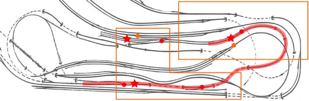
The figure above shows where the train would run back-and-forth. There are 2 small stations, one in the back and one in front. A small train, a Budd RDC-1, would run between both stations.
Hardware needed:
- 3 infrared-sensors. One in front of each station where the trains are to stop and one in the yard to park the train. I used TCRT5000 from http://amzn.to/1W5o3MQ.
- 5 turnouts need to be controlled to make sure that the automation proceeds as expected:
- There are 3 turnouts on the branchline where the train travels.
- There is one turnout in the branchline yard where the train is parked.
- There is one turnout going from the mainline to the branchline that will be locked so that no mainline train can affect the automation.
- One kid-friendly button needs to be mounted on a facade, probably close to the front.
- One master switch (to turn the automation on/off) needs to be mounted on the mountain panel.
- Two NCE Switch-It 8 to control the turnouts. Each card controls 8 turnouts and is actually shared with the other projects.
- One NCE AIU (auxiliary input unit) to report sensors and button states to the computer.
Visible automation:
- There's a little station on the branchline on top of Sonora and a few buildings in the back side. A train would run from one spot to the other, stop, wait for some time and then reverse direction.
- Once the train reaches the station, it stops again and sits idle for 5 minutes.
- Automation starts again when the kid-friendly button is pressed.
- Pressing the button when the train is moving or less than 5 minutes after arriving at a station does nothing.
Automation off:
- A toggle switch should be added on the mountain panel to turn the automation off.
- When the automation is turned off, the train goes back to the front station if it wasn't there yet.
- Once that is done, the train is parked in a select yard track available on the branchline.
- Any press of the kid-friendly button is ignored when the automation is stopped.
Train selected:
- Budd RDC with DCC & Sound, made by Rapido (16532).
You can see a video of an RDC on the branchline here: https://youtu.be/eezaCk7DK-0
It would look fairly similar.
21.2- Phase Exploration (2017)
Work on the Branchline started after the exploratory one for the mainline so pretty much everything explained in the chapter 16.2 - Phase Exploration for Mainline applies here.
The only difference was with sensors, and the block mapping.
IR Reflective Sensors:
The original intent was to use a reflective infrared sensor connected to the AIU01 to detect the train on the branchline. This worked in local tests with the exception that the train is not detected long enough, and most of the time the sensor was not read in time. The data sampling rate on the AIU01 is not fast enough and the train was frequently missed even when travelling at medium speed. The idea could still be worked in a different way so I'll detail it in an addendum at the end of this document.
Blocks for the Branchline Automation:
After experimenting with and realizing that IR reflective sensors would not work as expected, the plan was changed to use block detectors. Quite some time was spent understanding the block wiring on the Branchline, which led me to carefully document and understand the Branchline panel (see 11.2- Branchline Main Panel); eventually 4 suitable blocks were found to map the starting and reversing point of the automated route. The Conductor program was consequently updated.
21.3- Implementation in 2017
The implementation closely followed the initial plan with the small detail of using block detectors instead of IR sensors.
An NCE AIU01 is located under the branchline with the following mapping:
AIU01 address 48 for the Branchline sensors:
Bit |
JMRI |
Description |
Bit |
JMRI |
Description |
1 |
752 |
BL Parked B801 |
8 |
759 |
-- |
2 |
753 |
BL Station B821 |
9 |
760 |
-- |
3 |
754 |
BL Tunnel B850 |
10 |
761 |
-- |
4 |
755 |
BL Reverse B860 |
11 |
762 |
-- |
5 |
756 |
BL Reverse 2 B870 |
12 |
763 |
-- |
6 |
757 |
-- |
13 |
764 |
-- |
7 |
758 |
-- |
14 |
765 |
BL Activation Switch |
Entries in italics are planned and not wired yet.
The NCE Switch-08 controlling turnouts (installed in the Mountain Panel) controls the T324 turnout from block “BL Station” to block B322. This allows the automation program to make sure it is normal and never thrown during automation.
Few changes were made to this later. Most of the follow up work in 2018 was programming and fine tuning of the automation program. The Rapido RDC SP-10 needed some repairs, twice.
In 2019, we changed the engines to Rapido RDC ATSF. A dead spot appeared on the “BL Station” block so I resoldered a broken rail joiner. I also started looking in more detail at the way the branchline track is wired. The goal is to move the polarity inverter to specifically the part of the track that loops in the back. This project is elaborated more clearly below (see 23.3- Project: Power for the Branchline).
21.4- Ongoing Work (2019)
Plan for the branchline:
- Task 1: Solder broken track (done).
- Task 2: See 19.3- Project: More Blocks & Turnout Control for Branchline
- Check whether T810 and T820 work.
- Access to the panel (bring power tool).
- If they do, map them to a Switch-8 mounted next to the AIU.
- AIU move BLStation from input 2 to input 5.
- AIU pos 2: map terminal #20 (black / brown)
- Task 3: AIU Pos 6: Check whether terminal 1 (B830, White, Orange + Blue/White) would trigger.
- Task 4 -- see 19.2- Project: Power for the Branchline
- Understand B870 (done: goes up to Rodgers).
- Remove Lenz (done)
- Rewire B870 in 3(?) segments and power middle via the Lenz reverser.
- Both segments at BLRev2 and Rodgers should be aligned with the nearby track.
The key part for task 2 here is having T810 working, as it would allow the use of both yard tracks 1 & 2 and alternate departure of 2 trains.
B830 is a different topic. I’d like to have more visibility in the loop between the station and the tunnel block.
22- DCC Junior Engineer Day
GGMRC was running Junior Engineer Day in DC. This involved reconfiguring the layout panels to DC mode, a fairly complex and undocumented operation that I observed to be very error prone. The end of DC runs was dictated by a physical electrical split in the layout blocks.
Running a JED event at GGMRC involved a substantial amount of membership work and coordination:
- One member would distribute tickets to the public (tickets were free and simply served to give turn orders).
- One member would be manning the main DC throttle at the Mountain Panel. The kid running would choose one of the two trains waiting at the Stockton Station (always one freight and one passenger, placed on mainline #1 and #2). Once the train was selected, the member in control would align the Sonora turnout (where both mainline tracks merge) and release control of the train by turning on the power for the selected train’s block (either block B310 or B311). Once the train has cleared that block, its power toggle should be turned off again.
- One member would be in the back at the Valley Panel. Once the running train had passed the Tehachapi Loop, it would be controlled by the Valley’s throttle. The operator there would bring the train back and selected turnout T30 to bring it to the mainline #1 or #2 tracks. On the layout there would always be two trains of each type (two passenger, two freights). The operator at the Valley Panel would be responsible to get the current train and stop it back at the Stockton Yard’s mainline, then as the next train was picked up and left the station the Valley operator would bring the next train to replace the one that had left. This part particularly required coordination between both operators as it all depended on properly turning on and off the adequate blocks.
- On top of 3 active members/operators, the event would typically require at least 2 more members to take turns/shifts.
22.0- Initial Plan (2016)
Before the club shut down, I had started working on a solution to be able to run the operation in DCC. The solution consisted of an Arduino-based throttle that would control the selected trains via JMRI, a tablet for the Mountain operator to control the trains, and a second tablet for the Valley operator coordinating with the first tablet. The “dispatching” role of the Valley operator would be handled by the automation software and the operator would be there just to ensure proper working of the trains, and most important take care of derailments or other unexpected issues.
There are 2 key differences between running the event in DCC vs DC:
- Most DCC engines are programmed by default to have close-to-prototype progressive start and simulate brake inertia. These must be turned off for Jr Eng Days events.
- In DCC, there is no technical limitation that dictates the end of the kids' run. Instead I'd suggest a timer be used and each kid has a specific time to play with the train before the end of its turn.
Any other automation that uses the mainline would be stopped during Junior Engineer day. The branchline automation could still be running since it doesn't impact mainline activity.
Hardware modification would be split in 2 phases: Phase 1 would the minimum needed to make this possible knowing that operators would need to make sure the mainline was prepared appropriately (e.g. clear and all turnouts in the desired positions.) Phase 2 would add extra turnout control and block detection to remove the need for manual preparation or detect equipment left on track.
22.1- Phase 1
Hardware needed:
- 2 turnouts to control: 1 for Sonora and 1 in the back where mainline splits after the return tunnel.
- 5 block detectors: 1 on tunnel exit, 2 in the back to stop reserve trains and 2 in the front where trains are ready for selection.
- One NCE Switch-It 8 to control the turnouts, shared with other projects.
- Two NCE AIU (auxiliary input unit) to report sensors to the computer, one being shared with other projects.
Mandatory work specific for DCC control:
- A kids throttle is needed with a small arduino controlling the speed.
- A tablet for the docent to control which train is being run.
- Custom software to drive the tablet, the throttle and the trains.
Pictures from the early DCC Jr Eng Day experiment showing the home-made wooden throttle and the tablet interface for the operator:
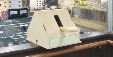
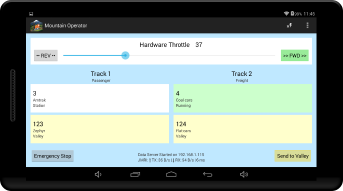
22.2- Phase 2
Hardware needed:
- 31 turnouts on the mainline to control.
- 30 blocks on the mainline to detect.
- An extra NCE Switch-It 8 for the turnouts.
- An extra NCE AIU for the block detectors.
We will probably never control every turnout or detect every block, however a rough estimate was that 10-15 of each would be relevant based on my recollection of derailments that I had seen happen because some turnout was left changed in the wrong direction or some car was left behind on the track.
Time wise the goal would have been to implement all of phase 1 modifications before the museum were to reopen. An important difference with the passenger or branchline automation was that the DCC Junior Engineer day required extra hardware (throttle, tablet) and software for the tablet.
Phase 2 hardware modifications could be done later as time permits.
22.3- Postponing
In 2017 I decided to de-prioritize this work in favor of focusing on reliability of the mainline and branchline automations. I also suggested changing the format of the event as the way it was handled by GGMRC was not, imho, quite optimal, but these changes were simply rejected as irrelevant.
One obvious issue I realized was the staff-intensive nature of the JED events, which technical requirements do not align with the currently available staff.
23- Ongoing and Future Projects
This section describes on-going or future projects, in no specific order.
23.0- Pending Work on the Layout
Trying to strive for a balance between work I want to do on the layout versus things I believe need to be done, coupled with their direct impact (either for operators or automation) and work complexity.
Here’s an updated list as of 2020-02-29 2021-01-18 2021-06-29 2023-03-28 2024-08-10:
Task |
Impact |
Work Load |
|
Finish DCC control Mountain Turnout Panel |
Need |
Low |
High |
DCC control Stockton Passenger panel |
Need |
Low |
High |
DCC block detection on Valley panels 1 & 2 |
Need |
Low |
High |
DCC block detection on Mountain panel 1 |
Need |
Low |
High |
Want |
Medium |
Low |
|
Fixing dead spot at Sultan |
Need |
Medium |
Medium |
Fix the Fairfield-Lodi approach Status: Replacing turnout motor for T905 |
Need |
Medium |
Medium |
Automation of Fairfield area |
Want |
High |
Very High |
LED Building Lighting: Update with LED lighting. |
Want |
High |
High |
Computer monitoring of all Circuit Breakers |
Want |
Medium |
High |
B91 Siding: Wall sign & turnout LED status. |
Need |
Medium |
Medium |
Update documentation with latest changes |
Want |
Low |
Low |
(all items done below) |
|||
Workbench: Install NCE + PR3 + LokProgrammer. |
Want |
Low |
High |
Vacuum layout & scenery [done by Orion |
Need |
High |
Very High |
Refresh “green” scenery (grass, shrubs, trees) [done by Orion |
Want |
High |
Very High |
Scenery on access panel in Fairfield [done by Orion] |
Want |
High |
Very High |
Automation software “Conductor” v2 |
Want |
High |
Very High |
Napa yard clean & usable by operators [done] |
Need |
High |
Very High |
Bridgeport yard clean & usable by operators [done] |
Need |
High |
Very High |
Layout “cab ride” Cameras & Display for Public [done] |
Want |
High |
High |
DCC Mainline turnouts for Napa yard approach [done] |
Need |
High |
Medium |
Grade crossing lights at Fairfield Station [done] |
Need |
High |
Medium |
Building Lighting: Install / power Cracker Jack sign. [done] |
Want |
High |
Medium |
DCC Mainline turnout for Bridgeport yard [done] |
Need |
High |
Low |
Adjust Grade crossing lights at Fairfield Station [done] |
Need |
High |
Low |
Bridgeport turnout: Replace the Fulgurex turnout [done] |
Need |
Medium |
High |
Stockton Station dedicated Circuit Breaker [done] |
Need |
Medium |
Low |
Bridgeport ballon track: Install DCC Auto-Reverser [done] |
Need |
Medium |
Low |
There are more tasks on my list (see sections below); these are all I’d consider important for now.
- Need/want column: This is highly subjective. A “need” item is needed for short or long term usage of the layout (even though that may or may not be obvious to Saturday Operators). A “want” item is something that would be nice to have.
- Impact column: “impact” is from the perspective of the Saturday Operators and/or the Automation from a public point of view, e.g. would people notice this work has been done.
Low impact does not mean the task is not important -- it’s the “behind the scene” stuff that enables more to be done later: I’ve had some plans for the automation from the very beginning, I focused on what was most critical at first, and have slowed down a lot in the implementation since then. It does not make the long term plan any less important, and having year to year incremental improvements is a good thing.
A lot of these “low impact” tasks would enable future automation work by detecting trains in blocks currently not monitored or enabling turnouts to be controlled.
For some of these tasks, I have already done a significant amount of preliminary research and I have the hardware for it.
I’ll detail most if not all of these tasks below.
23.1- Blocks and Turnouts Map
One project I started back in 2016/2017 is numbering all the blocks and turnouts on the layout. Having numbers for everything makes it easier to describe when talking to people. It’s also a requirement for my automation where I need labels and variable names.
Some parts of the layout already had block numbers and I’m keeping this numbering scheme intact as there are a few labels and inscriptions that refer to these block numbers of the layout.
Pre-existing numbering I could find:
- The mainline from Stockton Passenger Station up to Sultan has block numbers ranging from B01 up to B170 in a East-West running direction. All these blocks are mapped on the Valley Panel.
- The mainline from Stockton Passenger Station up to Bridgeport has block numbers ranging from B310 up to B450 in a West-East running direction. All these blocks are mapped on the Mountain Panel.
- The mainline uses a mostly consistent scheme where a x10 number represents the main track and x11 number represents a siding. For example B50 is mainline and B51 is a siding. The exceptions are B01/B02 and B451/B452 which represent track 1 (main) vs track 2 (siding).
- The yards have track numbers which simply differentiate the tracks within the yard (e.g. track 1 up to track 8 for the main Stockton Yard). There is no global numbering scheme.
I created an enhanced block numbering scheme to cover all the layout. Since the layout power districts match control panels, this creates a good opportunity to create blocks of numbers per panel:
- B01-B170: Valley, unchanged.
- B200-B240: Stockton Yard.
- B300-B451: Mountain, unchanged.
- B500-B520: Stockton Passenger Station.
- B530: Lodi.
- B600-B630: Roundhouse Yard.
- B700-B730: SIA / DFS.
- B800-B890: Branchline.
- B900-B930: Fairfield.
I have not numbered the Napa yard and the Richmond yard yet.
One big omission on this layout is a complete lack of turnout numbers. Operators regularly were getting confused when using the main Stockton Yard as there are no labels that can be used to match a physical turnout with the corresponding panel button. Most people like me just go by the schematics, but that is painfully not obvious to everyone.
The mainline is an interesting challenge as it has two numbering schemes that go in reverse direction: Valley numbers go up East-West and Mountain numbers go up West-East .
To create turnout numbers for the mainline, I thus decided to use the current running direction and apply a very simple rule: “the turnout number is the number of the block where that turnout leads into”. For example the Sonora turnout, in the current direction, leads to block B330. Consequently Sonora turnout is T330. It is the same number as the block where trains will run when the turnout is normal. This makes it trivial to figure out which panel contains a turnout toggle.
“B” numbers are blocks, and “T” numbers are turnouts.
The latest track plan with all the block and turnout numbers can be found at https://www.alfray.com/trains/randall/.
23.2- Project: More Labels & Documentation for Operators and Visitors
One of the things this layout seriously lacks is labelling and that’s one area I tried to focus early on. For operating the layout, there are not many labels on the panels to help identify the turnouts or blocks. And for visitors, there’s not a lot of information on the layout itself.
In this section, we’ll describe what work has been done in this regard and what’s left to do.
23.2.1- Labels & Documentation for Visitors
Originally there was nothing to even describe the layout in the room. The visitors should be able to learn how this layout came to be, and what it represents.
Wall History Map Display
Status: completed. High impact/priority.
A short presentation was created by combining the track map from Bob Hansen with the original’s GGMRC web site description of the Sierra Nevada & Pacific Railroad.
The result is this PDF file: Randall Map - Wall History Map Display 1b.pdf.
This provides a brief history of the railroad as well as a brief history of the room itself.
This was printed as a 17x11 flier and is displayed on the wall by the entrance.
A laminated copy of that was made by the museum staff and is displayed by the Mountain Panel.
Branchline Map and History
Status: to be done. Low impact/priority.
One could say the public at large doesn’t really understand the Branchline. It’s presence is not even well defined, as for most people it just looks like yet another track in the middle of the mountain, and I’d tend to think in general even the concept of a branchline is not well understood to begin with.
That’s unfortunate as the Branchline on this layout is relatively well documented. It took me quite some time to find the information as it was buried all over the place (sometimes quite literally), yet it’s really there, and I’ve put what I found in section 15- Branchline.
It would be worth creating a 17x11 flier similar to the “layout history” above giving some hindsight on what is a branchline, which track it is on this layout, and which actual California towns are represented.
Fascia Nameplates for Towns
Status: to be done. Higher impact/priority.
All the towns on the layout represent counterparts in California, yet that is nowhere visible to the public. Some of this is apparently on the control panels only.
What I’d envision here are printed fascia nameplates for all towns on the layout, especially the ones visible to the public:
- Stockton and its station (the San Joaquin Street station from 1900, not the more modern one from 1930).
- Fairfield and its industrial area.
- Sonora.
- Summit (likely related to Donner Pass).
- Tehachapi loop.
- Lodi (not visible to visitors).
On the branchline, we have the towns found in the Nevada County Narrow Gauge Railroad, namely:
- Angels Camp (often written as “Angel Camp” in the layout docs),
- The junction point to the mainline is likely Colfax.
- Oilville, that name appears on the paper label under the layout.
- Chicago Park, very close to Colfax; that name appears on the paper label under the layout.
- Smith Flat town, which serves the “Gravel Pit” and the “Red Dog Mine”.
- Bear River is likely a reference to Bear River Pines which is next to Colfax.
- You Bet town.
- Greenhorn Logging Railroad.
- Colemans, which appears on the NCNGR map, is likely Coleman.
Besides having nameplates, we could have a bit more details for each, either short snippets, or depicting their actual location on a California map.
The technique I used for the turnout number plates can be used here: print using a color laser on US letter-size card stock, then cut the labels using an x-acto knife. The labels can then be placed on the horizontal part of the fascia behind the glass windows, to be protected from visitor tear & abuse. For an example of the result, look at the turnout number plates for Sultan and T150/151.
23.2.2- Labels & Documentation for Operators
One issue I noticed in the old club and with current operators is that it’s often hard to figure which physical turnout is controlled by which physical toggle. I tried to address this from a few different angles: first a unified numbering system for all turnouts and blocks was created, see 23.1- Blocks and Turnouts Map. Then track plans and turnout number plates were printed.
Track Maps
Status: Complete.
Published track plans with the corresponding blocks and turnout numbers:
- Randall Map - Layout Map 3.pdf
- Randall Map - Track Plan + Sensors 8.pdf
- Randall Map - Stockton Yard Panels 4.pdf
- Randall Labels - Stockton Yards with Pix 5 b.pdf
Honestly I think the track plans are not even looked at by operators; I have yet to have anyone tell me they noticed them, even less found them useful.
Turnout Number Plates
Status: Partial.
Turnout numbers plates were printed for Stockton Yard and Valley Panel, with color-coded numbers plates next to the turnouts and matching ones on the panels.
The number plates for turnouts on Stockton Yard have had more success. I’ve also done the mainline around that yard.
There are similar number plates for turnouts on the Mountain Panel, however I don’t think anyone uses these.
The technique I used for the turnout number plates is simple: I created an SVG template and printed it using a color laser on US letter-size card stock (this provides some good color contrast and stability and seems better than home inkjet printers), then cut the labels using an x-acto knife. The labels are then placed on the horizontal part of the fascia behind the glass windows, to be protected from visitor tear & abuse. For yard turnouts, there are two labels, one next to the turnout itself and a matching one (same color) by the corresponding panel toggle. The yard labels use a consistent color scheme as a way to indicate which panel to use for which turnout.
The latest focus had been to label turnouts that have operational value:
- T450 for Bridgeport access.
- T150 / T151 / T160 for Napa access.
- T80 / T90 for that siding access.
Since the yard turnout number plates have worked well for Stockton Yard, we should expand that to other areas of the layout:
- Lodi panel.
- Napa yard panel.
- Richmond yard panel.
- Bridgeport yard panel.
These 3 latter yards are a lesser priority as they already have their track numbers printed on the plywood. However it would be nice to carry the consistency across all yard panels.
Balloon Tracks
Status: Partial.
To help operating the balloon tracks in Napa and Bridgeport yards, I created instructions for each panel:
Now that all these tracks are equipped with automatic polarity reversers, the instructions need to be updated and new labels printed.
23.3- Project: Power for the Branchline
The goal of this project is to understand and rectify some of the power for the branchline.
There are a few oddities or at least unanswered questions in the current setup:
- The entire branchline is powered through the Lenz Digital Plus LK100 polarity reverser. This seems like an unusual arrangement.
- According to the documentation I was able to find around, rail polarity is expected to match at the junction in Angels Camp / Sonora and differ at the junction in Rodgers. This is not what I observed.
- I cannot find a DCC bus nor actual track feeders in the track section between You Bet and Rodgers (blocks B870, B880, and B890). There are a couple track feeders but they are left dangling and not connected. ⇒ I would like to understand where block boundaries are, if any.
- Rationale: if this can be made into a block, it would form the ideal reversing polarity section by applying the Lenz Digital Plus LK100 only to that section, with polarity fixed and matching at both Angels Camp and Rodgers.
- Similarly, I cannot readily identify track feeders on the canyon side between Angels Camp and Smith Flat (blocks B830 and B840). There is one block power toggle on the panel, but I wasn’t able to properly follow the wiring.
- Rationale: I’d like to map this section with one or more BD20 block detectors. This requires understanding the block boundaries and track feeds.
Update 2019-03-11:
- I removed the Lenz Digital Plus LK100 which was connected in series with the DC/DCC bus relay. This removes the polarity inversion from the branchline, which means now polarity should be correct at only one side of the “reverse loop”. This is acceptable since we currently do not use the Rodgers junction.
- With the polarity reverser removed, measured rail polarity and found this:
- It is inverted at the Angels Camp junction with Sonora (B322). This is unexpected. According to the documentation I had found before, it should match here.
- It does match at Rodgers Junction. This is where I expected it to be inverted.
- Consequently I inverted the black/red DCC wires output of the DC/DCC relay powering the branchline. That fixes the polarity at Angels Camp and inverts it at Rodgers Junction.
- According to Mr. Perry schematics, at the Rodgers Junction the branchline powers the track till the F1 track of DFS. This does seem to be right. That means now all this part of the track has the wrong polarity with adjacent tracks. This is only acceptable as we currently do not use that section, yet would become an issue if we were to use it.
- There is a specific track feed for block B860 (the one where the automation stops at You Bet).
- There is a specific track feed for block B870 (just after You Bet). I traced this to connect to B890 just before the Rodgers Junction relays.
- There are no track feeds for block B880, the part where the branchline loops around Mr. Perry’s coal mine. There are however track feeders dangling from the track, left exposed and connected to nothing (which is a good way to create accidental shorts). My guess is that power comes from rail continuity.
- To prevent anyone from shorting, I temporarily disconnected the track feed for block B870. This also unpowers B880 and B890 up to the SIA/DFS track.
The next steps are:
- See if I can properly isolate B870, B880, and B890.
- Power B870 to match the Angels Camp polarity.
- Power B890 using the reverse polarity (to match the mainline at Rodgers Junction).
- Power B880 through the Lenz polarity reverser.
I further noticed that throwing T324 (interchange between Branchline and B322) now shorts the Branchline. That is wholly unexpected as power should come from the Branchline. That requires more investigation and I recall seeing a hand-drawn power routing from Mr. Perry that I should dig up and look at.
Update 2019-04-09:
See blog post https://www.alfray.com/trains/blog/randall/2019-04-09_branchline_interchange.html for context.
The TL;DR is that I remade a hand-drawn schematics I found from Mr. Perry describing the power routing at B322 between the Branchline and the Mainline, and I think it’s fine and should be kept intact. See the post above for a discussion. I think the next tasks should be:
- [Task 1] Remove the LK100, and later use it to control only a sub-section of the branchline.
- [Task 2] I should try to understand why the resistance between both rails is so low when there’s no power on the layout. The only way I know of doing that is by unplugging the DCC feed, and then starting isolating blocks one by one. (Update 2019-10: I should measure that again, since in between I have removed all the DC bias resistors).
- [Task 3] Since this polarity match is expected but not observed, that would be the next thing to understand and fix. The polarity should be made to match at Sonora. Then I can take care of the Rodgers Junction side later.
- [Task 4] Next fix is to understand and fix the short that happens when throwing T324, as it is clearly not tied to the whole power scheme. The first thing to do is understand is what exactly is shorting here as that is not clear.
Update 2024-07-29:
See blog post https://www.alfray.com/trains/blog/randall/2024-07-29_branchline_power.html for details.
Essentially we addressed Task 1 and 4 above:
- All the “mountain” branchline is now powered directly without the polarity reverser, and it’s powered using the same polarity as the mountain approach on T322/T324.
- The LK100 polarity reverser is now only powering the blocks B870-B890 -- anything past the mountain up to the Rodgers’ Junction.
- We also added toggle to turn the blocks B870-B890 off. That will prevent the automation from entering that section by mistake.
- The short from T324 has been identified -- it was due to a fix I made that was bridging the inner rail, because there was an issue with the frog power. We traced that one down to the Tortoise SPDT not powering the frog properly, and changed the Tortoise for T324. Unfortunately we altered the finicky behavior of that turnout so now some stuff derails there.
Next tasks:
- [Task 1] Add an NCE BD20 sensor on the block B870 and map it to the automation. That way we can keep it on all the time, and I can change the automation to stop the train if that block becomes active by mistake.
- [Task 2] Either fix, amend, or replace the turnout at T324 to prevent further derailments.
- [Task 3] Change the power routing at Rodgers’ Junction. I need to think about it more but I think we need a block just after the bridge, powered by the SIA. Then the actual branchline power would start after the bridge.
23.4- Project: More Blocks & Turnout Control for Branchline
The goal of this project is to add more block detectors and DCC turnout control on the Branchline.
Track diagram (blue is mainline, green is branchline):
Currently the Branchline has the following block detected:
- B801 a.k.a. “BL Parked”, the first yard track where the automated RDC is parked.
- B821 a.k.a. “BL Station”, the Angels Camp / Sonora station.
- No block detection in the canyon / tunnel and through Smith Flats.
- B850 a.k.a. “BL Tunnel”, the small tunnel between Smith Flats and You Bet.
- B860 a.k.a. “BL Reverse”, the section of track at You Bet (between the tunnel and the inoperative turnout).
- No block detection after You Bet.
And for turnouts:
- None on the Branchline panel.
- T324 (the interconnection between mainline and branchline) which opposite side is on the branchline.
What I’d like to add:
- A block detector for B870 (after You Bet), to be able to identify over-runs of the automation and do an emergency stop of the engine.
- One or more blocks between the station and Smith Flat through the canyon and the first tunnel (B850). Right now if the engine gets stuck here, we have no way to detect it. Of note: I do not know exactly how many blocks there are, if any, or even what are their boundaries. In my notation, B830 denotes “after the station” and the canyon, B840 would be Smith Flat (it had a panel so it must have its own power routing), and B850 denotes the tunnel between Smith Flat and You Bet (already mapped). I don’t really know what exists for B830 or B840.
- B802 and B803, the second and third yard tracks where more engines could be stored.
- DCC control over T810 and T820, to be able to use the corresponding yard tracks. These are Tortoise.
Parts I would not touch:
- No DCC control for T830 as it has a broken point and I don’t know how to fix it.
- No block detection for B823 (since it leads to the broken T830).
Rationale: “if” automation had control over yard tracks #2 and #3 that means we could have 2 or 3 trains ready in the yard, align the turnouts and run that one. So it’s a bit of variety as not always the same train would get out and run on the branchline.
Risk factors:
- First the turnouts need to work, be fully functional and most importantly reliable. E.g. close properly, no broken point.
- We need to experiment by toggling them and making sure a train can go through them dozens of times a day without derailing.
Parts which are not risk factors:
- An NCE Switch-8 can be used. It is compatible with the Tortoise turnouts used here. I would not use an NCE Button Board since it has reliability issues and thus would not provide control through the (hidden) Branchline panel.
- Block detection is not a risk factor for the yard as I know there are block toggles for these tracks.
*Current* AIU01 address 48 for the Branchline sensors ( → to be rewired):
Bit |
JMRI |
Description |
Bit |
JMRI |
Description |
1 |
752 |
BL Parked B801 |
8 |
759 |
-- |
2 |
753 |
BL Station B821 moves to #4 |
9 |
760 |
-- |
3 |
754 |
BL Tunnel B850 moves to #8 |
10 |
761 |
-- |
4 |
755 |
BL Reverse B860 moves to #9 |
11 |
762 |
-- |
5 |
756 |
BL Reverse 2 B870 (not used) |
12 |
763 |
-- |
6 |
757 |
-- |
13 |
764 |
-- |
7 |
758 |
-- |
14 |
765 |
Activation Switch (obsolete) |
The desired NCE AIU01 mapping is as follows (planning ahead, implementation may vary).
Entries in bold already exist but would change position. Entries in italics need to be added.
*Desired* AIU01 address 48 for the Branchline sensors:
Bit |
JMRI |
Description |
Bit |
JMRI |
Description |
1 |
752 |
B801 Yard Track 1 |
8 |
759 |
B850 “Tunnel” |
2 |
753 |
B802 Yard Track 2 |
9 |
760 |
B860 “You Bet” |
3 |
754 |
B803 Yard Track 3 |
10 |
761 |
B870 after You Bet |
4 |
755 |
B821 “Station” |
11 |
762 |
B880 polarity reverser |
5 |
756 |
B823 |
12 |
763 |
B890 Rodgers Junction |
6 |
757 |
B830 “Canyon” |
13 |
764 |
-- |
7 |
758 |
B840 “Smith Flat” |
14 |
765 |
-- |
Alternatively I could keep the current wiring (with positions 1-4 used) and just tackle new blocks as I go along.
23.5- Project: Power for Stockton Passenger Station [done]
The goal of this project is to properly power the Stockton Passenger Station using its own power district.
The main motivation is to remove the power linkage to the yard / mainline blocks. Shorting on the mainline still creates odd issues.
Explanation
Please read chapter "8- Stockton Station" for an explanation of how the passenger station power wiring was designed.
The short version is that this was a DC-driven design. The power for the whole station depends on the turnouts that connect it to the mainline in the East or West approach.
When the layout was converted to DCC, that design was vastly misinterpreted or at least misrepresented. The explanation was “blocks to the East for DC, blocks to the West for DCC”. Essentially that means in DCC the station is connected to the Stockton Yard or the two mainline blocks in front of it depending on the position of the T03 / T04 / T05 turnouts on the mainline or the Roundhouse T604 turnout.
Unfortunately that part of the mainline is used by Saturday operators to set up their trains. The side effect of this is that the passenger station is trivially shorted when operators short while setting up their trains or momentarily when the mainline turnouts are being thrown. When this happens, the block detection is affected as it cannot properly detect trains that are located on blocks not powered.
Ironically the design of the passenger station includes its own power feed, and has two convenient terminal positions to wire it. This is currently unused. The solution is to use it.
Details
- Add a new NCE EB1 circuit breaker on the existing row of circuit breakers (already ordered).
- There is some obvious benefit at placing the circuit breaker with the existing ones. Easier to wire and easier to check if activated.
- Connect the EB1 to Booster 4. See chapter "5.4- DCC Power" for a list of booster/power districts. That would share it with the Mountain 2, Bridgeport, and SIA/DFS which have very little to none occupancy at the moment.
- Draw a DCC bus to the Station West feed.
- Length from circuit breakers to panel should be about 24 ft for the DCC bus.
- I’d likely not use a relay for the DCC.
- Align all the Passenger Station blocks to the left (East).
This would also power the 3 small spurs to the east of the station (B505, B506, B507) which are currently not connected. However I have no intention of controlling them (no block detection, no DCC turnouts).
Update 2021-01-04: This has been completed.
Details at Blog 2021-01-04 - New Power Districts for Fairfield and Stockton Station.
A dedicated EB1 circuit breaker is installed by the command station:
DCC is now provided to the Stockton Station using a dedicated power district on the “West” terminal:
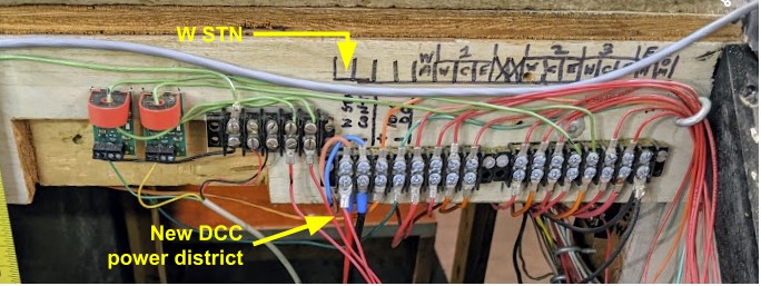
The station panel can now have most blocks set on the “West” left side, with the exception of the AW one that still requires to be on the “East” right side to get the proper power routing -- not sure why exactly. Also the upper garage tracks don’t have power yet, contrary to what I expected from the schematics. The proper panel configuration should now resemble this:
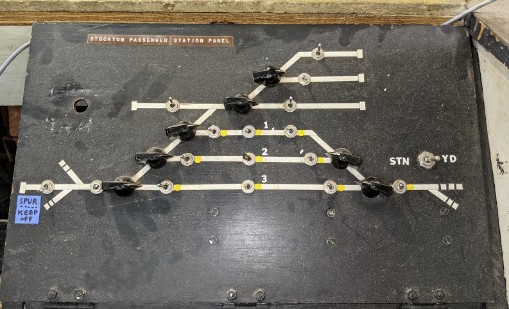
I checked and as expected shorts in the Stockton Yard no longer influence the trains in the Stockton Station. The automation works unchanged.
Possible updates (low priority);
- Dust off that panel!
- Understand why AW needs to be powered East (right side).
- Understand why the three garage tracks B505, B506, B507 do not have power.
- Both of these were implied from the schematics I followed… Consequently I’d need to update schematics accordingly if they are not accurate.
23.6- Project: Turnout Control for Stockton Passenger Station
The goal of this project is fairly simple: add an NCE Switch-8 to the station panel to have DCC control over the station tracks.
To give an overview of the area, this is my map from 2018 (the block boundaries are approximations, when present):
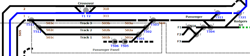
The station has 3 tracks. Even though it’s not depicted as such on that map, each station track has 3 blocks. Right now only the first track B503 can be used in automation.
This project would allow the use of the two other tracks in automation, thus allowing us to store more trains that are “ready to go”. This can be used both to add more variety to the automation and/or to allow trains to rest more.
A minor sub-task is to label the turnouts on the panel.
In the spirit of having MVP vs final phases, I’d skip using an NCE Button Board at first as they can be better switched using the ACCY mode on the NCE controllers.
DCC turnouts to be controlled with one Switch-8 (planning ahead, implementation may vary):
T501 |
T502 |
T503 |
-- |
T505 |
T506 |
T512 |
T513 |
According to my 2018 map & notes, all these turnouts are Tortoise, and can thus be driven directly by a Switch-8.
Note: T504 is actually on the Mountain Panel. Technically when I renamed all the turnouts in 2018, I should have numbered it T32x instead of using the T5xx numbers.
The Switch-8 would be powered using the DCC Turnout Power Supply. I can pick that up on the Mountain Turnout panel which is nearby.
23.7- Project: Block Detection for Stockton Passenger Station
The goal of this project is to wire the remaining blocks of the Passenger Station. Out of the 3 main tracks, only 2 blocks have detectors on the first track, plus the outgoing track (“Approach West”). This allows detection of the current Passenger train as it arrives to the station and its middle stopping block.
Each station track has 3 blocks (East, Center, and West). There is already an NCE AIU01 mapping the East + Center for the first track. The rest should be wired. This requires adding 8 x BD20 sensors.
The desired NCE AIU01 mapping is as follows (planning ahead, implementation may vary).
Entries in bold already exist but would change position. Entries in italics need to be added.
AIU01 address 50 for the Passenger Station Panel: (actual 2018)
Bit |
JMRI |
Description |
Bit |
JMRI |
Description |
1 |
784 |
B503a (East) |
8 |
791 |
B502a |
2 |
785 |
B503b (center) |
9 |
792 |
B502b |
3 |
786 |
B503c (West) |
10 |
792 |
B502c |
4 |
787 |
B504 “Approach West” (East) |
11 |
793 |
B501a |
5 |
788 |
B510 “Approach East” (West) |
12 |
794 |
B501b |
6 |
789 |
-- |
13 |
795 |
B501c |
7 |
790 |
-- |
14 |
796 |
Motion Sensor |
Note that there’s a slight discrepancy with my current block/track map:
There’s no “B510 Approach East” on my map. I took that label from the Passenger Station panel. I believe this is referring to what I labeled B505 on my map.
For this I need 11 BD20 sensors -- the motion sensor connects directly to the AIU-01 and does not need a block detection sensor. These are actually 3 blocks detected, thus 8 more need to be added. Ideally I’d design a little wood board with all the components, all wired at the workbench, that can be easily installed and wired using spade connectors on the spot on terminal blocks at the bottom and top of the boards. Two designs come to mind, either with both blocks + turnouts, or as separate boards.

or
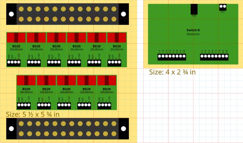
Update 2023-09-10:
A BD20 sensor was added for block B504. It’s currently mapped as NS784 (AIU 50, bit 1) simply because I reused one of the old activation button wires which I left in place. If and when the scheme above gets implemented, it should be remapped according to the sensor map table above.
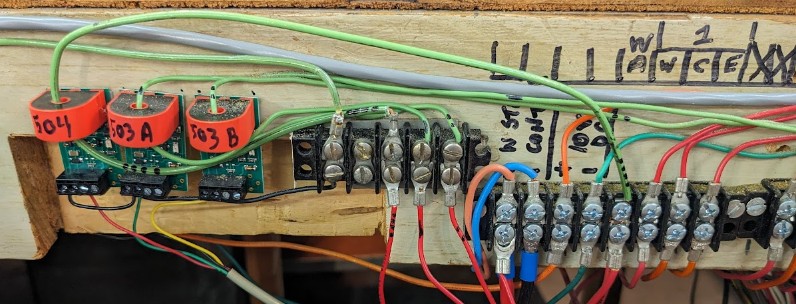
23.8- Project: Power for Fairfield
The goal of this project is to properly power the Fairfield Industrial Yard using its own power district.
Power would come from a dedicated booster (see 5.4- DCC Power) directly. I would not use an NCE EB1, for this one, instead I’d use a DCC Specialties Circuit Breaker (already ordered). An NCE EB1 has been mounted with the other circuit breakers next to the command station..
On the panel, a DCC Specialties Frog Juicer is used to power the reverse section. This is why it is recommended to use a matching circuit breaker instead of the NCE EB1.
There is one wiring issue that needs to be fixed between turnouts 3 and 4 on the Y2 track. From my analysis back in 2015, this always resulted in a conflicting DCC polarity. Track feed could not be followed as it was buried under the plywood, but this needs to be understood and/or rectified. It may have to do with frog power routing of the turnouts.
Phase 1:
- Mount an NCE EB1 next to the command station, and bring DCC to the panel to a terminal block. [done]
- Modify the power selector:
- Connect DCC to the “Yard Cab” input of the large power selector.
- Disconnect the power from Block 130 or Block 110 going to the power selector.
- This basically converts the power selector into an on/off toggle with 3 improperly labeled inputs.
- Eventually convert the power selector into an on/off toggle.
- There is no plan to add block detection nor DCC turnout control for this.
- There is no plan to fix the turnouts besides their known current status. See 10- Fairfield Industrial Yard for details.
- There is no plan to even power the turnouts at first. They would be manually set in the desired position.
- The goal of the automation (see next project) is to use the current track as-is.
23.9- Project: Automation for Fairfield
Task: Experiment with visual-based automation on fixed track pattern (no turnout control). 2 possible timer shuttle automations at first.
Details: https://www.alfray.com/trains/blog/randall/2019-02-10_fairfield_industrial_yard.html
Details in this doc are located in chapter 10.5- Future Plans.
23.10- Project: Fix Mountain Panel Toggle Panel
- Currently disconnected (except DCC turnouts)
- Cleanup: Remove 2nd duplicated power line for the NCE Button Board, use the same as the existing Switch-8 power line.
- Cleanup: Do we need the (obsolete?) little lights?
- Yes for those that indicate when a block is mapped on the other block panel.
- No for anything else. Any wiring we could remove that simplifies this panel would be good to have.
- Mountain Panel: Wire for Switch-8 + cleanup wiring.
- Need to rewire current panel to have room to place a second Switch-8.
- Need to change rotary toggles wiring to route turnouts directly to the new Switch-8.
- Need to add more relays to handle Fulgurex turnouts.
- Decide whether we want to continue supporting the rotary toggles.
- If yes, the issue is that the NCE Button Board is simply not reliable.
- If no, we have extra cabling and work done for a feature we don’t use.
- In the spirit of phased implementation, I’d posit we don’t need to support a Button Board for new turnouts, but we should keep the ones already wired. Revisit later if assumptions change.
Update 2020: A second Switch-8 has been added to power turnout T450 for Bridgeport (with NCE Relay, going to Fulgurex). There is no NCE Button Board nor any physical toggle control for that one.
23.11- Project: SIA / DFS
- SIA: Single-track shuttle trolley automation. No turnout control. IR or visual control.
- SIA / DFS… Details: https://www.alfray.com/trains/blog/randall/2018-11-22_more_automated_routes.html
23.12- Project: Valley Panel
- Valley Panel 1: BD20 block detection.
- Valley Panel 2: BD20 block detection.
- Valley panel: Wire Sultan / Richmond for DS64 (delay).
- Valley panel: Wire for Switch-8 (delay, low priority).
Delay means the task is to be delayed before more important tasks are achieved.
The NCE Switch-8 / Button Board needs more work before I can safely apply it to actual used panels. The most logical possibility is to use an Arduino Nano connected to the Switch-8, but this needs to be experimented with something that can be dispensable first (e.g. Lodi).
The alternative considered is to use a Digitrax DS-64 instead of the NCE Switch-8 (which I have already ordered). Supposedly it could handle our non-momentary toggles inputs. This needs to be experimented with before modifying the panel.
23.13- Project: Mountain Panel
- Mountain Panel 2: BD20 block detection.
23.14- Project: Lodi Panel
- Lodi panel: Wire for Switch-8 (low priority, deal with this later).
Obsolete Project Description:
However since this panel is easily accessible, with more modern wiring, and ironically much less used and not as critical as other panels, it’s a good place to experiment with replacement for the problematic NCE Button Board.
As explained in chapter 15.2.5- Somewhat Correcting the NCE Button Board, the current technology choice of using the NCE Switch-8 combined with the NCE Button Board fails since, first, the board does not support the kind of rotary toggle used on this layout and, second, the Button Board / Switch-8 seem to stop cooperating after a certain elapsed time.
Experimenting with the Lodi panel would be done in the following order:
- Add an NCE Switch-8.
- There are 8 turnouts on the Lodi panel.
- 7 of them are Tortoise slow-machines, which are directly supported by the Switch-8.
- 1 of these turnouts has a broken point and should not be used until repaired.
- The 8th turnout uses a twin-coil (the junction with Fairfield) and is currently not powered.
- Thus are 6 operational Tortoise turnouts that can be controlled.
- At that point they can be used via the Pro Cab ACCY button.
- Add an NCE Button Board, reprogrammed either using my firmware or the one from NCE that supports non-momentary contacts. The board should first be used as-is, per specs, to see if the unresponsiveness issue arises again.
- If it does, an alternate idea is to replace the NCE Button Board by an Arduino Nano providing the same functionality, as described in https://www.alfray.com/trains/nce_button_board.html#h.yvp8cjti449e. I still have the one I used for that experiment, and it’s readily usable as a drop-in replacement to the Button Board:
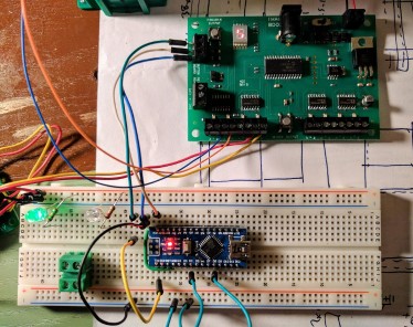
- An alternate approach I started experimenting with is to use an Arduino and an RS485 interface. This can be used to simply send NCE turnout commands directly on the NCE Cab Bus, as a Pro Cab throttle does.
Explanation can be found here: https://www.alfray.com/trains/nce_cab_bus.html
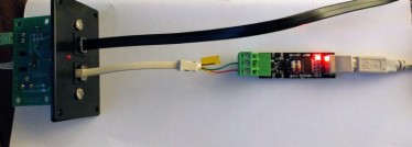
- At that point, one may wonder why even bother with the NCE system. An Arduino could be used to simply send turnout control commands to the JMRI server over Wifi using the JMRI JSON protocol. It is certainly easier than using RS485 to talk to the NCE Cab Bus. The downside is that the panel would be inoperative as long as the JMRI computer has not finished booting up.
- Another alternate approach is to use a Digitrax DS64. One can drive up to 4 turnouts (Tortoise only), so two would be needed here. They can be configured for either twin-coils or slow-motion turnout motors. Tortoises are known to be supported; Fulgurex motors are not supported yet may marginally work (See post on Digitrax DS64 test for details).
Update 2021: The explanation above is outdated in the sense that I now know how to properly convert these panels to DCC:
- The resolution as of 2021 is to just use NCE Switch-8 boards without any button board to control DCC turnouts. The panels are to be left in place yet become non-functional. Instead, it becomes a requirement to have a visual help indicating the DCC turnout numbers somewhere physically close to the actual turnouts.
- Another experiment / realization in 2021 is to not use the DS64 for Fulgurex motors. The DS64 is ok for Tortoise turnout motors.
That being said, converting the Lodi panel to have DCC control of the turnouts via an NCE Switch-8 is still pretty much a task I’d like to see happen at some point. It’s low priority though compared to other projects.
23.15- Project: Access to Richmond / Napa from Mountain [done]
Right now access to Napa / Richmond is done by aligning T140, “Sultan”. One issue is that the siding has developed a dead spot, which needs to be addressed. The other issue is that control of T140 is done from the Valley Panel, which is on the opposite side of the room.

The suggested way to access Napa / Richmond is going to be using T150 or T151. The task involves:
- Fixing the dead spot before T140 on the Sultan siding.
- Fixing T151: one side of the cross-over does not throw. There is also no power when thrown. [fixed]
- Bring local control over T150, T151, and T160. Either add it to the Richmond panel or create a new panel, and then remove them from the Valley Panel. [fixed]
- Optional: Instead add a display on Valley Panel showing whether the track is aligned on T150 / T151 / T160. Either via a tablet display, or using 2-color LEDs on the panel.
Erratum: in the original track plan, I got some turnout numbers wrong. The turnout next to T151 leading to the Richmond Yard is T162. We generally don’t use it. The turnout at the end of the Napa lead (Block B160) leading to Richmond Yard is T160, and that’s the main one we use to switch.
Update 2020-03-06: Experiment with using a Digitrax DS64 to control these turnouts via NCE controller. This is now operational and we can control T140 (Sultan), T150, T151 and T160 from any NCE controller. See the section above 19.2.6- To convert a Turnout to DCC using Digitrax DS64 to understand their limitations.
Update 2020-03-08: Experiment at home with signals to be placed next to the turnouts, to indicate when they are left in their thrown/diverging state. This will be installed on the Mainline-to-Napa turnouts.
Update 2020-03-07: Created a display sign to remind operators of the turnout numbers to use and how to throw them using their NCE controller. Use this link to download a printable PDF.
Update 2020-03-15: Fix the turnout T151 with Allen’s help.
Update 2020-05-24: Install Turnout Light Indicators for T151 and T160. T150 has not been equipped yet.
Update 2021-01-09: Install Turnout Light Indicator for T150.
To add the LED indicator:
- Drill a small 3/32” hole from the top of the layout (or ⅛” but not larger).
- It can be useful to use a larger bit like 5/32” from the bottom to enlarge the plywood passageway.
- Prepare an assembly with a small red LED soldered with a 2.2 kΩ resistor. Wrapped in kapton tape for isolation.
- Solder some wires at the bottom.
- Drop the LED from the top.
- The wires get connected to the 6-position terminal driving the Tortoise or the fulgurex.
- One side goes to the frog (the output from the slow motor contacts).
- The other side goes to either rail A or B as needed to trigger it when turnout is thrown.
- LED polarity does not matter since we connect to DCC.
- Important consideration: the LED will be in reverse voltage for half the DCC signal duration. Red LEDs can supposedly stand a large reverse voltage whereas green / orange / blue ones cannot [citation needed]. A typical design workaround is to add another diode in reverse to the LED to avoid that reverse voltage.
T150 terminal from left to right: 1 Green + 2 White = turnout control; 3 Black + 5 Red = Rails A/B; 4 Green = frog.
The status LED has wires gray+yellow, connected to the green frog + red rail.
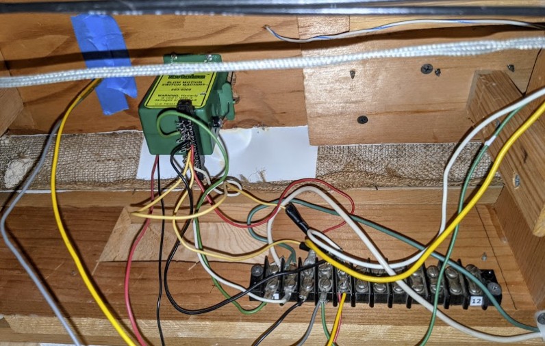
23.16- Project: NCE AIU01 to Monitor EB1 Circuit Breakers
The layout power is split between four NCE boosters and ten NCE EB1 electronic circuit-breaker as indicated in 5.4 DCC Power.
This is a common practice on such a large layout such that a short does not affect the totality of the trackage. When operators use the layout, they can trivially identify a short by either the lack of power (duh) or by looking at the blinking light on the circuit breakers.
When remotely monitoring the automation, that doesn’t quite work though. Ideally I want the automation computer to be able to monitor and record the status of the circuit breakers.
I looked at various solutions. The “obvious” one is to use an Arduino or similar. However my design philosophy has been to try to reduce the amount of custom hardware if possible. It then occurred to me, we can simply use the same sensor cards that are already in use on the layout, namely the NCE AIU01 boards. These have 14 input sensors, are connected to the NCE cab bus, and can be polled by JMRI as sensors. The refresh rate is rather low (1-2 seconds) but that’s enough for our needs.
The AIU01 inputs are designed to monitor a pin that is grounded, typically by a relay, or a transistor.
The EB1 circuit breakers have two terminals designed to wire an external LED. The LED is on by default, and turns off when a short is detected. It does not just turn off, it blinks as the EB1 tries to repeatedly reapply power to check if the shorts has been fixed.
The idea is to power an opto-coupler using the EB1, which will in turn close an input on the AIU01.
Update 2019-09-29: First proposed version (see below).
Update 2020-02-04: I have experimented with the NCE AIU+EB1 at home. (Updated details below).
The proposed solution is to use dual-channel optocouplers to connect the EB1 LED output to the AIU inputs.
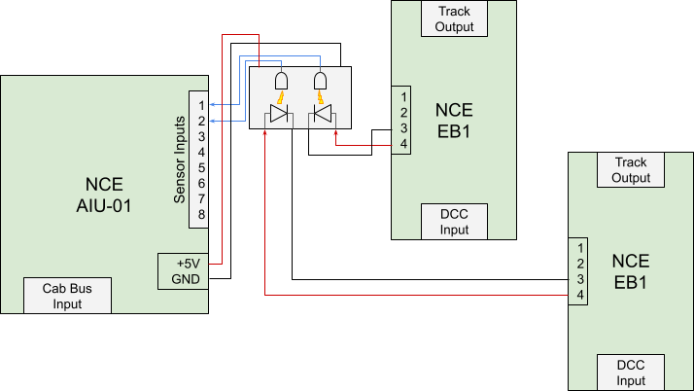
Here are the details, as updated on 2020-02-04:
- HCPL2630/TLP2630/VO2630 dual-channel optocouplers.
- The NCE EB1 has a 4-position terminal. Positions 3 and 4 are designed to connect an external LED. According to the EB1 doc there’s already a 300Ω resistor, and it outputs 5 V, thus around 17 mA.
- The NCE AIU01 inputs are actually pull-ups, activated when driven to ground. This is a perfect match for the output of these optocouplers.
Details on the EB1:
- Check your EB1 board Revision! There are at least 3 board revs out there -- at Randall, I have boards with Rev B and with Rev C. They are easily distinguishable: the Rev B boards are definitely older, they use jumpers instead of the dip switch of the newer revision, and they do not feature the PIC 12F683 microcontroller.
- The EB1 doc indicates a LED (-) should be on terminal pos 4 (outer side) and thus logically the (+) on the inner terminal pos 3. Contrary to what the EB1 doc says, on the EB1 I took to experiment with, Terminal 3 (inner, lower) is LED -, and Terminal 4 (outer, lower) is LED +. This may not be a “documentation bug” as it is more likely a mismatch between the board revision I was looking at versus the doc I was looking at. Thus the warning above: always check your board revision against the documentation you’re reading.
- The on-board LED and the external LED terminal are connected to a PIC 12F683 (pdf link) on Pin 7 (GP0). The on-board LED is connected between that same pin and Vdd (positive power supply) [Reminder: Vss=Ground, Vdd=+Voltage]. Thus keeping GP0 low would by default light up the LED, which seems to be the default behavior.
- EB1 LED is ON by default (no short) ⇒ Opto output = Low ⇒ AIU bit == 1.
- According to the EB1 doc: “300Ω 5 V” = 17 mA.
Details for the optocouplers:
- Toshiba TLP2630 (direct download datasheet) or Vishnay VO2630 (datasheet).
- IF max is 20 mA. Recommended input current is 5 ~ 6.3 mA..
- Experimentation shows that a 470Ω resistor worked well to activate the LED side of the optocoupler.
- The optocoupler output is an open-drain. In practice that means it needs to be pulled up to Vcc, and it is grounded when activated.
- Experimentation shows a pull-up of 1kΩ or 2.2kΩ worked well.
- The AIU has a 10kΩ pull-up on each input. My 2.2kΩ pull-up thus goes in parallel, and makes for an equivalent 1.8kΩ resistor. At 5V, that’s 2.7 mA. The datasheet recommends the output pull-up resistor to be in the 330-4.4kΩ range and a typical sinking current of 13 mA.
- Like the 6N137 (its single channel counterpart), the 2630 optocoupler works as an inverter, that is the output is low when the input is high.
Since the EB1 LED is on by default, the optocoupler output will be low by default, which is seen as a 1 by the AIU. My preference would be to have them reversed, that is I’d prefer the AIU input to be high by default to avoid sinking current through the optocoupler all the time.
With all this into account, the schematic is thus the following:
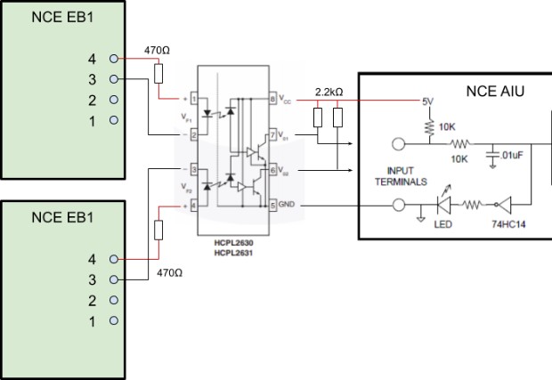
When there’s a short, the EB1 turns off the status LED, and thus the AIU input is read as a 0. However, being a self-reset device, the EB1 just keeps trying to re-apply power every few seconds, which makes its status LED blink briefly -- this has a nice side effect allowing for easier visual identification. Due to the NCE cab bus pathetic refresh rate for these AIU01 cards, there is a tiny possibility that each AIU read would be aligned on the time where the LED blinks, and thus the shorting status would be missed. This needs to be identified and tested first. If that’s an issue, it can be solved by just adding a capacitor on the output like I did to solve the missed button presses issue.
This is the 2630 optocoupler I plan to use (the prefix name depends on the supplier):
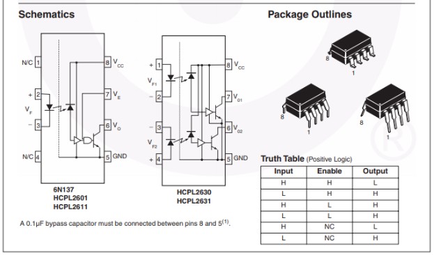
It’s also possible to use the 6N137 single-channel optocouplers instead, one per EB1 output to monitor.
Two EB1 are connected to each opto-coupler as follows:
- EB1 #1 terminal 4 (outer) = LED+ ⇒ 470Ω ⇒ Opto pin 1 // pin 7 ⇒ AIU pin 1
- EB1 #1 terminal 3 (inner) = LED- ⇒ Opto pin 2
- EB1 #2 terminal 4 (outer) = LED+ ⇒ 470Ω ⇒ Opto pin 4 // pin 6 ⇒ AIU pin 2
- EB1 #2 terminal 3 (inner) = LED- ⇒ Opto pin 3
- Opto pin 8 Vcc to AIU +5V from 7805
- Opto pin 5 GND to AIU GND
AIU01 address: 62
JMRI Address / Number = (AIU01 address - 1) * 16 + (AIU01 input - 1)
JMRI Address from 976 (62:1) up to 989 (62:14), included.
Mapping from NCE AIU to EB1 (or others):
JMRI address |
AIU pin |
EB1 |
Optocoupler |
976 |
1 |
P1 V1 |
O1 pin 1+2⇒7 |
977 |
2 |
P1 STKYD |
O1 pin 3+4⇒6 |
978 |
3 |
P2 V2 |
O2 pin 1+2⇒7 |
979 |
4 |
P2 NAPA |
O2 pin 3+4⇒6 |
980 |
5 |
P2 TOWN LODI |
O3 pin 1+2⇒7 |
981 |
6 |
P2 FAIRFIELD (*) |
O3 pin 3+4⇒6 |
982 |
7 |
P3 MTN |
O4 pin 1+2⇒7 |
983 |
8 |
P3 BRN RCH-2 |
O4 pin 3+4⇒6 |
984 |
9 |
P4 MTN-2 |
O5 pin 1+2⇒7 |
985 |
10 |
P4 BRPORT |
O5 pin 3+4⇒6 |
986 |
11 |
P4 SIA RND |
O6 pin 1+2⇒7 |
987 |
12 |
P4 STK STN (*) |
O6 pin 3+4⇒6 |
988 |
13 |
O7 pin 1+2⇒7 |
|
989 |
14 |
O7 pin 3+4⇒6 |
The AIU has 2 terminals of 8 positions each (1 GND + 7 inputs). I’d like to find 7 or 8-wire ribbon cables and use that to connect a little board containing all the optocouplers to the AIU and attach them both together. I should look at old floppy or ATA ribbon cables that I have around.
Originally I was going to use AIU inputs 13 and 14 to monitor mains voltage. One for the layout mains, and the other for the DCC switch. Instantly that reminded me of the is_computer_on() API joke… since this AIU will be read by the PC that is powered by the DCC switch, there’s little point. They would always be on. Still I should wire optocoupler #7 in case I want to add 2 inputs later.
(*) EB1s for P2 Fairfield and P4 Stockton Station do not now exist, located with the other EB1s for consistency.
23.17- Project: Update Building Lights to LEDs
The current building lights were discussed above in 5.2- Building Illumination / Lights Power Supplies -- the system is composed of an antique custom power supply designed in 1997 and mostly failing to deliver 15V DC to a distribution panel. Out of the 30 possible outputs of this panel, 4 were found to be actually controlling something visible. Half of that panel is not wired and not connected to anything, and for most of the other half we don’t know where the wires go, and whether the buildings there are connected, or have functional light bulbs. In the few buildings where we can find lights, 12V bulbs are used.
The proposed update has been discussed in this blog post -- notably the issue with the cost of the system.
The summary is:
- We’d used the Woodland Scenics “Just Plug”Lighting System:
- We would first start with one starter kit and one starter location,
- Then later if deemed satisfactory, we would expand to other areas of the layout.
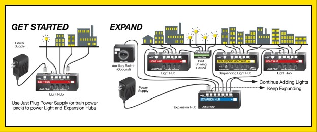
Let’s detail this.
Starter Phase : Starter Kit + Fairfield
The hardware for the first phase would be:
- The starter Lights & Hub Set, composed of one hub with 4 ports and 2 LEDs.
- One pack of 2 extra LEDs.
- One power supply brick.
Cost: MSRP is $55, slightly cheaper on ModelTrainStuff.
Without the port sharing device, we can connect 4 LEDs.
Next we identify 4 buildings we want to light up in Fairfield. If memory serves, 1 or 2 already have lights, so we can start with these and replace the current old 12V bulb by a LED.
Our first task is to:
- Measure coverage per LED. E.g. do we want 1 LED per building, or more?
- Keep in mind that room lighting is typically on every day, so we want the effect visible “during daylight”.
- Do we need to black out the interior?
- Do we need to add a diffusion material?
Our secondary task is:
- Enumerate all buildings in Fairfield that could use some lights.
- Compute the number of needed LEDs and deduce the number of port sharing devices we need.
Next step:
- 1x up to 4x Port Sharing Device to connect 4 more LEDs onto 1 port + 4 extra LEDs.
Cost: MSRP is $20-ish per sharing device and its LEDs.
With one port sharing device, we can connect 7 LEDs total to that hub. With 4, we can connect up to 16 LEDs. The single power supply brick is enough to power all that and even more.
Before moving to the next phase, we’d finish adding lighting to all buildings in Fairfield that deserve it.
Note that I never mentioned the current 15V DC building power supply. I’m rationalizing we’re not going to use it. It’s easier to power the Just Plug system using its own power brick. We actually do not foresee the need to “remote” control lights from the Stockton lighting panel.
Expansion Phase : Branchline + Stockton Town
Once we are satisfied with the Fairfield area, we can use that knowledge in other places.
On the Branchline, we have two places with light bulbs which are worth converting. Because they actually have lights, means they are conduits for wiring, and thus updating the wiring should not be too complicated:
- On the back of the mountain, the little side building by the Smith Flat area (out of the canyon tunnel).
- This is very easy to access from the top.
- Next to Sonora, we have one little light stand. This may be harder to convert to LED.
- It would be nice to have lights in both the Sonora station and some of the buildings in YouBet.
- This may require drilling to add lights under.
Hardware needed for that is 2 light hubs (1 shared between Sonora + Smith Flat, one for YouBet). For power we have a 12 V AC aux bus in the area, or we can use 1 power supply brick + 1 expansion hub.
Stockton Town is our final target.
For that one, I figure we need 1 or 2 light hubs, and anywhere between 8 up to 16 LEDs.
2~4 LEDs would be dedicated to the main Stockton Station (probably powered by its own Port Sharing Device stuck inside the station building).
There are many shops in the town, and ideally we would add power to their lower floor / windows. I figure we budget to light up 8 of them. We would have to examine each building in more detail to get the whole picture first. We can do 2 sets of 4 buildings, one per port sharing device. I’ll leave this voluntarily open here and we can revisit once we get ready for it and have more details.
23.18- Project: Workbench with NCE PowerCab, Digitrax PR3, LokProgrammer
Our programming track sits on the workbench in the back, and is currently powered by a wired NCE Power Cab. That cab can be used by the operators to program their engines. I have an NCE USB interface to use it directly from the nearby Linux laptop with JMRI 5.
I also acquired a Digitrax PR3 a few years ago and an ESU LokProgrammer recently. Right now using them requires unplugging the NCE Power Cab, and powering the track from the Digitrax or the ESU one.
The goal is to mount them somewhere on the bench and have an easier way to toggle between them.
Hardware Needed
The current NCE Power Cab is just sitting on the bench. There’s a little UTP panel fixed on the top of the workbench that provides power and connects to the track. Since the handheld controller is the main control box, all we have is a wire going to the UTP panel.
For the Digitrax PR3 and the ESU LokProgrammer, I envision we would screw them to a little wood board, and then either mount it somewhere out of the way or leave it on the side of the workbench.
The only thing we need is a selector for the track connection. We have 2 wires to switch, and 4 possible connections, thus a simple 2P4T rotary selector (2-poles 4-throw) will do the job:
- Inputs (2 wires each):
- DC / analog throttle.
- NCE Power Cab (programming track)
- Digitrax PR3
- LokSound Programmer
- Output:
- 2 wires to the programming track.
We already have a power strip that can accommodate the corresponding power supplies, and the computer is within a foot or two of reach. I don’t think we need anything fancy for power. We just keep them plugged in all the time using their provided power bricks -- we already turn on the power strip only when we need the programming track. We don’t need to switch on/off the power depending on which device is in use.
We’ll connect the rotary selector to a 12-position terminal block, that way the various programmers can be connected only to the terminal block, making it easier to change connections without having to solder wires directly to the rotary selector.
Here’s a simple sketch of the install and how it will all fit on the workbench:
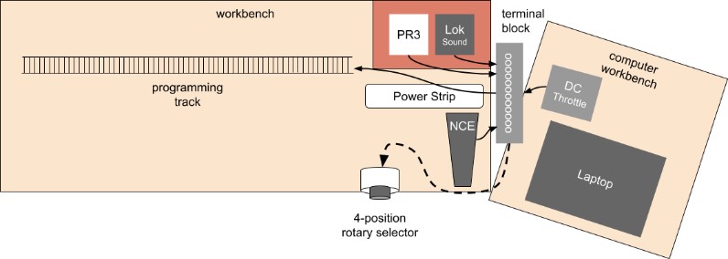
We’ll use a terminal block, with the rotary selector connected on one side, and the electronic equipment connected on the other side. This way we don’t have to change any soldered connection on the rotary selector when we want to connect or disconnect equipment:
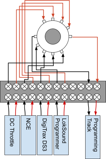
Software Needed
Both the Digitrax PR3 and the ESU LokProgrammer could potentially work with JMRI on Linux, but that would use only the “generic DCC” portion and thus not provide more benefit than we get with the NCE solution.
The whole point is to benefit from dedicated programming of the Digitrax or ESU decoders, and for that we need their corresponding custom software, and that’s Windows only.
That laptop I’m using next to the workbench happens to be my backup for the main automation computer, so whatever I do, I will keep the Linux part intact and fully functional.
I’d expect the PR3 and the LokSound programmer USB interface to just be a basic serial-to-USB, either a FTDI or CP2102 or similar. We would never use them both at the same time, but it would be nice if we could leave all 3 USB cables plugged in all the time. That’s going to depend on how well behaved their proprietary software is
The solution I have in mind is:
- Plan A: Can I use their proprietary software under Linux with Wine and still have USB support?
- Plan B: Dual-boot Linux or Windows, and use a small dedicated Windows 10 partition just for the Digitrax and LokProgrammer software.
If I can stay on Linux only, I’ll do that, as I’d rather not have to support maintaining Windows there.
24- Known Issues
Everything ages and requires periodic maintenance, and this layout is no exception.
This section describes the parts of the layout track that have known issues. The goal is to repair over time, depending on priorities, time, and skills. Right now the priority is to first fix anything that affects the automation, followed by anything that affects mainline running during Saturday Ops.
This is sorted by order of block/turnout number and/or decreasing priority.
Symbols: ☹ Broken / to be fixed. ✘ Temporary fix. ☑ Fixed.
Affecting Automation:
- ✘ T320 (cross-over on curve after Stockton station):
- ✘ 2019 - First started derailing. [Fix] Spiked the throw bar.
- ✘ 2019 - Later turnout toggle on Mountain panel shorting the whole turnout power supply. [Fix] Disconnected. 2019 Details here. Should be fixed so that we can use the panel again.
- ✘ 2021 - Some trains short. [Fix] Spiked throw bar needed adjustment. 2021 Details here.
- ☑ B321 mainline between Sonora and T322: dead spot. [Fix] Resoldered. 2021 Repair report.
- ☑ 2023 Re-happening. [Fix] Resoldering a second time, and a third time.
- ☑ T322 (from main to branchline): Turnout sticky throw bar. [Fix] Cleaned. 2018 Repair report.
- ☹ T370: Currently spiked. Would like to have siding back to functional for automation.
- ✘ T370-T371: Broken rail joiner. [Fix] Temporary solder, should be done better. 2018 Details here.
- ✘ T371: Currently spiked due to floating throw bar. Siding is unused due to automation summit passenger station.
- ☑ B350: Block 350 intermittently dead/powered. [Fix] Resolder track joiner. 2019 Repair report.
- ☹ T830 (branchline going into station): Broken turnout bar (diverging route never used because of that). 2019 Details here. Don’t know how to fix it so I won’t touch it.
- ☑ B821 (branchline before Sonora station): Dead spot. [Fix] Resoldered joiner. 2019 Repair report.
- ☑ Stockton Station powered by B10-B20 tracks.
- 2018- This affects automation when Saturday Ops short the yard or the mainline when setting up their trains. Desired fix is to isolate station in its own power district. 2018 Details here.
- ☑ 2021- [Fix] Stockton Station now has its own power district. 2021 Details here.
- ☑ Motion Sensor dislodge by visitor. [Fix] Printed enclosure + fix to railing. 2021 Details here.
Affecting Saturday Ops:
- ☑ Dead spot on B02 (mainline in from of Stockton Station). 2021 Details here. [Fix] 2023 Repair report.
- ☑ Intermittent dead spot on B310/B02 between T01/T02 (cross over in front of Stockton Station). 2023 Repair report.
- ☑ Short on Stockton Yard track #6. 2022 Details here.
- ☑ Short on Stockton Yard track #8. 2022 Details here.
- ☑ T05 (main to siding in front of Stockton yard): Stopped working. [Fix] Switch machine lost contact spring. 2018 Repair report.
- ☑ T06 (main to siding in front of Stockton yard): Turnout sticky throw bar. [Fix] Cleaned & repaired. 2019 Repair report.
- ☑ T111 (in front of Lodi). Steam engines stall there, or typically derail. [Fix] Spiked throw bar (floating), 2022 Repair report. [2nd Fix] Mended turnout, 2022 Repair report.
- ☑ B320 Dead spot. [Fix] Resolder rail joint. 2021 Details here.
- ✘ T130 (main to Industrial City) [Fix] Frog hardwired for normal. 2018 Details here. Was having a 100-150 ohm resistance when going through the twin-coil switch. Proper fix is to replace switch machine or resolder + CRC 2-26 the contacts. Will not fix for now as we have currently no intention of using this turnout.
- ☹ T150 (main to siding just before Sultan): Engines stall temporarily on frog.
- ☑ T151 (from Napa to main, before Sultan): Dead track in turnout. 2019 Details here. 2020 Repair report.
- ☹ T160 (start of mainline siding at Bridgeport): Panel toggle broken, does not always toggle.
- ☑ T161 (end of mainline siding in back): Regular stall of steam/diesels.
- ☑ 2018- Switch machine contacts high resistance. [Fix] Swapped Fulgurex for another unused one. 2018 Repair report.
- ✘ 2021- Problem developed again. [Temporary Fix] Point temporarily spiked by Allen 2021 Report.
- ☑ 2022 - [Fix] Definitely fixed by rewiring power feeders 2022 Repair report.
- ☹ Napa yard track #1: No power on 3 end stubs, has turnouts not powered and actually not even wired!
- ☑ Napa yard track #3: No power. [Fix] resoldered. 2020 Repair report.
- ✘ Napa yard warping. 2019 Details here. [Fix] 2020 Repair report.
- ☑ Napa yard: Polarity auto-inverter for Napa yard balloon track.
- ☑ Bridgeport yard: T450 now has remote DCC control.
- ☑ Bridgeport yard: T450 Fulgurex was slow and overwhelming power supply. [Fix] Replaced Fulgured. 2021 Details here.
- ☑ Bridgeport yard switch #1 (entrance) dislodged point. [Fix] Replaced point. 2021 Details here.
- ☑ Bridgeport yard: Polarity auto-inverter for balloon track #1 (using the Dual Frog Juicer as Auto-Reverser).
- ☑ Bridgeport yard: Polarity auto-inverter for balloon track #2. Changed Hex Frog Juicer to Dual Frog Juicer.
- ☑ Bridgeport yard: Cleaned all track, verified all yard turnouts work as desired.
- ☑ Fairfield: Grade Crossing lights & bell.
Other known issues:
- ☹ Stockton Station mainline cross-over:
- ☹ Shorts when thrown. Some throw bars do not move.
- ☹ T01 (left on at cross-over in front of Stockton Passenger Station): Engines stall temporarily on frog.
- ☹ T02 (right top at cross-over in front of Stockton Passenger): Broken turnout bar.
- ✘ T80: Engines stall temporarily on frog. [Fix] Changed to T70 by selecting a different booster for B80.
- ☹ T90 (behind McDo): Engines stall temporarily on frog.
- ☹ T110 (from station at block 120 back to main, in front of Lodi). Broken turnout bar.
- ☹ T120 (from main to Fairfield station). No power for turnout. Would like to have siding for automation.
- ☹ T373 or T380 before Shed (issue not seen in a while): Engines stall temporarily on frog.
- ☹ T400 (Walong siding start): Switch machine disconnected. Does not have a throw arm.
- ☹ T410 (Walong siding end): Never seen used. Ever.
- ☹ Napa A: Broken turnout bar when entering the A loop on Napa (diverging route never used).
- ☹ Branchline: Currently unpowered on B870 (after You Bet), B880 (polarity reverser), B890 (Rodgers Junction). See 23.3- Project: Power for the Branchline above.
- ☹ Richmond Yard:
- Loss of power at every manual turnout.
- Out of the 2 powered turnouts, one has a broken switch coil machine. 2018 Details here.
- ✘ Scenery / Building lights
- ☑ In 2015, I “magically” fixed the building lights which had been reported broken for many years by tracing the power supply… and plugging it in.
- A lot less lights are visible these days. Figure out which buildings have lights which are not working.
- Figure out which ones do not have lights yet could be easily added.
- ☑ 2021- Label Lighting Panel. 2021 Details here.
- ☹ Fairfield Industrial City (see details here):
- Currently not powered. This is a larger project as it was never completely converted for DCC.
- In 2015, I started rewiring the turnouts. This is about 75% complete.
- Estimated 25% of the twin-coils turnouts have problems (dead coil, broken point, broken aux contacts).
- Fix power to blocks in Industrial City. Notably the way the Y is wired can never work in DCC (polarity inversion conflict). It just needs a simple polarity inverter (e.g. frog juicer) for a typical Y setup to make it work.
- Both mainline turnouts to get in and out of Fairfield are non-functional.
- ☑ 2021- Fairfield Industrial now has its own power district. 2021 Details here.
- ☑ 2021- Cleaned up one track in Fairfield Industrial to make it usable. 2021 Details here.
~~
~~
Page of