Automation: Arduino and NCE |
2016-05
In this article, I'll explain how to control an NCE system using an Arduino. This is a follow up to an earlier article I wrote that explains the inner workings of the NCE USB interface.
The layout automation I had done so far involved a computer running some script driving the animation either by interfacing to JMRI or directly to NCE over USB. However, for my latest project, I did not want to have a computer running. I wanted a system driven by an Arduino that would directly control an NCE command station.
Note that here I am explicitly not interested in the Arduino providing DCC power & commands to the tracks. The trains are solely controlled by the NCE command station. The Arduino operates like an NCE controller, exactly like an operator would do with an NCE ProCab.
In the past at the Randall museum in SF I used a Raspberry Pi connected to an NCE system via an NCE USB interface. At home I use a similar setup but using a cheap laptop. In both cases the computers run Linux and JMRI so I can control the system using the JMRI WiThrottle protocol over wifi or via a Python script run directly via JMRI. The WiThrottle protocol allows a program to control any number of trains. The JMRI scripting in Python has the extra advantage of allowing a program to have access to any sensors, routes or blocks defined in JMRI. The downside is having to take care of a computer, which means extra maintenance and complexity. That's where Arduinos are good, in the case where you have a single fixed task. They are easy to program, quite versatile, and at the same time fairly maintenance free -- once your sketch is programmed, just power up the Arduino and it will do its job. Once done, just pull the plug, no need to deal with boot up times and shutdown procedures.
Before going into too many details, here's a small experiment I made at home that illustrates this and a few other things.
The first version was based around a DigiX:
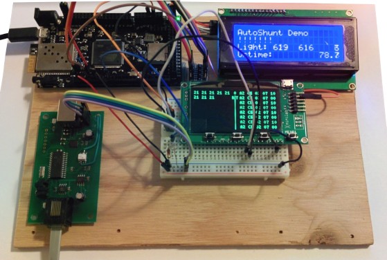
which I then updated to use an Arduino Mega and more peripherals, as can be seen on this video demonstration:
In this setup, we have an Arduino Mega 2560 controlling:
- A train via an NCE USB interface.
- The NCE module is connected to an NCE DCC Twin (my command station/booster) which is of course connected to the tracks.
- A 2-line LCD display via I²C (SainSmart I2C 2004 20x4 LCD).
- A 2-relay board to control the turnout (SainSmart 5V 2-channel solid state relay).
- An IR reflective sensor to detect the position on the engine (TCRT5000).
- An Xmega XMiniLab from Gabotronics displaying the NCE serial protocol.
The Arduino sketch used on that video is available here on BitBucket.
Now let's see how to build this piece by piece.
Arduino and LCD
This is the easiest part. Sort of. If you have never connected an LCD to an Arduino, here's a very short primer.
First, you must be aware of the "logic level" of your Arduino. Devices like the Mega or the Uno use 5V on their input/output pins. However devices like the Due or clones like the DigiX run using 3.3 V. That's a very important detail since trying to bring 5 V on the input/output pins of these devices will cause them some sort of damage.
How do you know which one supports what? First it's clearly written in the specifications, for example the page on the Arduino Due and the one on the Digistump DigiX indicate this very clearly. Second, a simple rule is if the device runs with an ARM processor, it's pretty much guaranteed to be using 3.3V logic levels.
On the accessories side, an LCD like the one I used clearly indicates it requires 5V logic. Same goes for the relays board.
What should you do if you have for example a DigiX with 3.3V logic levels and an LCD that requires 5V? That's simple, this requires using an extra 5V/3.3V logic level converter to connect the LCD to the DigiX as I did in the first version of this experiment.
Now to continue on the primer, regarding LCD screens. There are a few form factors out there: 1 line, 2 lines, 4 lines, 10 characters wide, 20 characters wide, green or blue backlights. There are also the graphic dot matrixes ones, very convenient if you need to display curves and not just text. Now the thing is that the text displays are typically controlled by a 16-pin bus, which is of course quite inconvenient to connect to an Arduino. Instead there exist small add-on boards that allow an Arduino to drive the LCD via the 4-pin I²C bus. I²C is nothing more than a serial link. You can either buy the LCD board and the IIC/I²C board separately and solder them together or you can buy a board like the SainSmart LCD2004 that already has the add-on module on the back, which is what I did; it looks like this:
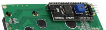
Here you can see that the LCD uses an IIC (parallel data, 16-pins at the top) with an add-on "IIC/I2C" board. It features an NXP PCF8574T to convert to I²C, which spec is here: http://www.nxp.com/documents/data_sheet/PCF8574.pdf
The nice thing with the I²C is that it's a bus, which means several devices can share the same serial connection. Devices are identified by a 1-byte address and that address is fixed by the add-on board in this case. You need to know the address of the board, and according to the SainSmart page and the Amazon comments, it could be either 0x27 or 0x3F. How do you know which one it is for your module? It's all indicated in the spec above in figure 10: the PCF8574T will use 0x27 and the PCF8574AT will use 0x3F. On some of the IIC/I2C add-on boards, the 3 least significant bits of the address can be changed, typically default to 111 and changeable by cutting or soldering a trace on the board.
LCD connection to Arduino Mega
I'm using the Arduino Mega 2560. You can find the pinout here: http://pighixxx.com/megapdf.pdf
For I²C, we need 4 pins: Ground, 5V, SDA (serial data) and SCL (serial clock).
My version is a Mega revision 3 and it looks like it has 2 I²C buses on the headers but that's not true: SDA is on pin 20 and SCL is on pin 21. On the pinout you may see there are also SDA and SCL pins next to AREF, but these are the same pins as 20 and 21. This Arduino has a single I²C bus.
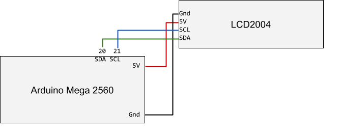
On the IIC/I²C add-on card, you'll find similar pins: Gnd, 5V, SDA, SCL. Just connect each pin to its equivalent:
- LCD GND ⇒ Mega GND (for example just below pin 52 or 53).
- LCD 5V ⇒ Mega 5V (for example just above pin 22 or 23).
- LCD I²C SDA ⇒ Mega pin 20 SDA.
- LCD I²C SCL ⇒ Mega pin 21 SCL.
Now let's program the Arduino to use this. The Arduino IDE 1.6.5 already has the library you need to drive the LCD in IIC mode. However what we need is a small extension to drive it via the I²C bus, and this is not included in the Arduino libraries by default. There are also a few out there with confusingly all the same name.
I used the LiquidCrystal_I2C library provided on the SainSmart LCD 2004 web page: look for a link called "Download Link for LCD2004", extract the RAR and take the two LiquidCrystal_I2C files (.h and .cpp) and place them in your Arduino Sketch (I have a copy in my git project on BitBucket).
Once we have this, driving the LCD is real easy and is done that way:
#include <LiquidCrystal.h> #include <Wire.h> #include "LiquidCrystal_I2C.h"
// set the LCD address to 0x27 for a 20 chars and 4 lines display LiquidCrystal_I2C lcd(0x27, 20, 4);
void setup() { lcd.init(); lcd.display(); lcd.backlight(); lcd.setCursor(0,0); lcd.print("Print on line 0"); lcd.setCursor(1,0); lcd.print("Print on line 1"); }
void loop() {} |
LCD connection to a DigiX
I started this way, so I'll just put this here without too many details in case it's of any use.
I originally started this project using a DigiX by Digistump, a Due/Mega clone with about 99 IO pins, several UARTs, a couple I²C buses, an SDCard and a Wifi module. Unfortunately it runs using 3.3V logic levels which is a problem with both the LCD and the relay board. Then in the middle of my work I unfortunately screwed up the wifi module to the point of making it inoperable. I revisited my project specs and decided I wasn't making use of the extra features so I went back to an Arduino Mega, which turns out to be a much cheaper board anyway.
The DigiX uses 3.3V logic levels. There are two I²C buses, one on pins 20/21 like a Mega and the other one on pins 70/71 (SDA1, SCL1). The EEPROM is on the I²C bus on pins 20/21 so no matter what, never connect anything that provides 5V signals on these pins, as it's clearly stated that will damage it. To avoid that I used the other I²C bus on pins 70/71.
I thought about powering the LCD using 3.3V instead of the recommended 5V but that didn't work. The display was erratic and the backlight did not light up.
So instead I used this logic level shifter (there are a bazillion to choose from, they are all the same, either called I2C logic level converter or TTL logic converter or shifter… all the same stuff).
It's very simple: connect one side to the 3.3V pins of the I²C on the DigiX and the other side to the 5V pins on the LCD.
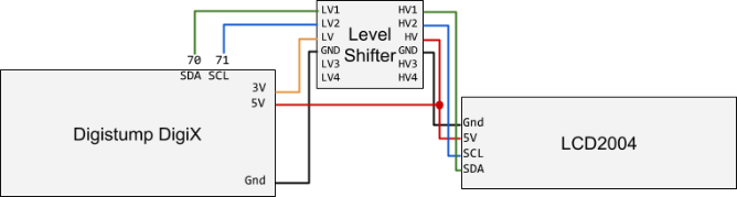
Pinout details from LCD/I²C ⇒ [Level Shifter] ⇒ Digix/I²C
- LCD GND ⇒ H GND ⇒ L GND ⇒ DigiX GND on nRF pin 1 (in front of pin 24).
- [Level Shifter LV] ⇒ DigiX 3.3V from nRF (in front of pin 28).
- [Level Shifter HV] ⇒ DigiX 5V next to pin 22.
- LCD Vcc (5V) ⇒ DigiX 5V next to 23.
- LCD SDA ⇒ [HV2 ⇒ LV2] ⇒ DigiX 70 SDA
- LCD SCL ⇒ [HV1 ⇒ LV1] ⇒ DigiX 71 SCL
LCD/I²C Pins |
[Level Shifter] Pins |
Digix/I²C Pins |
LCD GND |
⇒ [H GND ⇒ L GND] ⇒ |
DigiX GND (e.g. nRF pin 1) |
⇒ [Level Shifter LV] ⇒ |
DigiX 3.3V (e.g. on nRF header) |
|
⇒ [Level Shifter HV] ⇒ |
DigiX 5V next to pin 22 |
|
LCD Vcc (5V) |
DigiX 5V next to 23 |
|
LCD SDA |
⇒ [HV2 ⇒ LV2] ⇒ |
DigiX 70 SDA |
LCD SCL |
⇒ [HV1 ⇒ LV1] ⇒ |
DigiX 71 SCL |
Programming the DigiX to use the LCD uses exactly the same API as explained earlier, with the sole difference that the Digistump extension to the Arduino IDE already provides the missing LiquidCrystal_I2C library. So all you have to do is include the <LiquidCrystal_I2C.h> header.
Arduino and Relays
Since in this demo I had a single turnout, I chose to control the Atlas twin-coil turnout directly using relays rather than using an NCE Snap-It module or using an Atlas DCC control unit.
The operation of a twin-coil turnout is fairly simple: two coils are used as magnets to pull a pin in one direction or another. The pin moves the turnout. The coils must be energized only very briefly (I used 150 ms for example) otherwise they will overheat and burn out. The power for the coils typically comes from an accessory transformer pack. Some twin-coil turnouts can be energized using AC, others DC, others both. The kind I use (either Atlas or Bachmann) seem to work better with 16 V AC.
I choose to use the SainSmart 5V 2-channel solid state relay. Now there are a couple things to mention about it:
- It's a solid state relay, not mechanical, which means it's silent.
- The relays on the board are Omron G3MB-202P which spec can be found here.
Now that last detail is important
The Omron G3MB-202P supposedly requires 5V in input but they work fine when the relays are powered using the 3V pin from the DigiX.
These however have an important limitation: the supported load in the spec is only AC. They internally use phototriacs, and a TRIAC, although designed to switch AC can also in theory switch DC, which a small catch: triacs are latching devices. Once triggered, they will only release the output (load) once the current or voltage drops under a certain level. The spec of the G3MB-202P indicates this is 1V. In an AC load, that occurs naturally with the AC cycle. In a DC load, it doesn't, which means triggering the SSR will turn on the load but it will never turn off even when the relay input is released -- and in this application that will definitely fry the coils.
So this relay board works for me because I use the 16V AC from an accessory power pack to power the Atlas twin-coils, and these SSR will properly release on AC, but they won't on DC.
If you need to drive your twin-coils turnouts in DC, you need a different relay, for example the SainSmart 8-CH SSR 5A DC-DC 5V-220V SSR. When you get these boards, look carefully at the specs of the relays if possible.
Connection is fairly trivial, the relay can be controlled using any of the digital IO pins and the Mega has a ton of them.
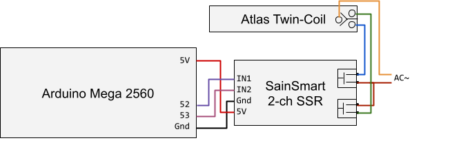
Please note that the Arduino is entirely separated from the AC accessory power. The solid state relays provide opto-isolation.
Controlling the relays is trivial. In this case the relays need to be triggered about 150 milliseconds to trip the twin-coil in the desired position.
#define RELAY1_PIN 52 #define RELAY2_PIN 53
#define RELAY_TIME_MS 150
void setup() { pinMode(RELAY1_PIN, OUTPUT); pinMode(RELAY2_PIN, OUTPUT); digitalWrite(RELAY1_PIN, LOW); digitalWrite(RELAY2_PIN, LOW); }
// Direction: 0=Normal (PIN1), 1=Reverse (PIN2) void set_turnout(int direction) { int pin = direction ? RELAY2_PIN : RELAY1_PIN; digitalWrite(pin, HIGH); delay(RELAY_TIME_MS); digitalWrite(pin, LOW); } |
Arduino and IR Reflective Sensor
In the demonstration I made, I use an infrared-reflective sensor to detect the position of the engine at a specific place on the track.
I first used an LDR (light dependent resistor) for the task. These are commonly found on grade-crossing circuits where 4 LDRs are located, 2 on each side of the grade crossing to detect the passing trains. The common issue with LDRs is calibration as their resistance varies not only with the passing of trains but also with ambient room illumination.
Infrared sensors solve this by reacting to infrared light instead of a broader visible spectrum. A typical setup is to have a LED that emits infrared located on one side of the track and the infrared photodetector on the other side. This detects when an object cuts the infrared beam.
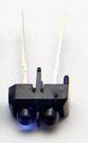
An infrared reflective sensor works similarly but instead the emitter and the receiver are next to each other. The receiver detects when the emitted infrared bounces off on a surface in front of the sensor. They both look like LEDs (see below) but only one is really an emitter and the other is a photodetector.
The model I chose is a TCRT5000 clone. You can find the Vishay spec here.
What you want to look for in the spec is the max current on the emitter and the ideal current on the receiver side.
The model I got is nothing more than 2 separate LEDs stuck together in a flimsy small plastic shell. You could easily remove the plastic shell and mount them in any way that makes sense on your layout. My idea was to have them under the track with the LEDs flush with the ties, pointing upwards.
The photodetector on the TCRT5000 varies its current based on the amount of light received. No light, no current; lots of light, more current. The amount of light that bounces and the collector current depends on the distance between the detector and the object. The nominal distance is 2 millimeters and experimentation showed that 5-6 mm was usable but something like 10 mm would be too much. Since the collector current is what varies and the Arduino's analog input measures voltage, we just need to place a resistor in series. And the good news is that we don't have to use an external extra resistor, we can just use the one built-in the each Arduino's analog pin: they have internal pull-up resistors.
The Arduino Mega's spec puts the internal pull-ups at 20-50 kΩ which is a good match for us.
In the end, that's the schematics we get:
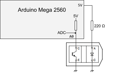
That does mean that the value measured on the ADC is high when there's no infrared being received. The value lowers when we detect an object, and the amount depends on the amount of light reflected, which depends on material and distance.
Here's the Arduino sketch needed to use this:
#define IR0_PIN 0 #define IR0_THRESHOLD 700
int ir0_activated = 0;
void setup() { pinMode(A0, INPUT_PULLUP); digitalWrite(A0, HIGH); }
void loop() { int a = analogRead(IR0_PIN); if (a < IR0_THRESHOLD) { ir0_activated = 1; } if (ir0_activated) { ir0_activated = 0; // Do something } } |
In the actual code I use a window to compute a moving average on the last 10 values. The activation boolean makes sure this is seen as a flag/toggle: once the value goes below the desired threshold, we remember that the sensor was activated and then only reset it once the sketch uses that information.
Arduino and NCE USB interface
Now we're getting to the most important part since this is how we're going to control our trains or accessories via DCC.
First, if you haven't read it yet, I recommend you look at my page explaining how the NCE USB interface works.
This details the interface card and how easy it is to interface with an Arduino.
I'll give a primer here, just read the other page for all the details.
This is what the NCE USB interface looked like originally:
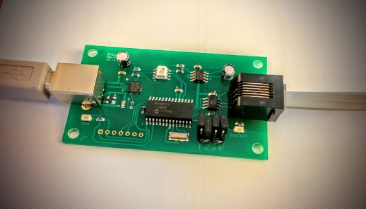
Normally, one side plugs to a computer via USB. The other side plugs into an NCE command station via the RJ12 jack.
The board is actually powered by the USB and works like this:
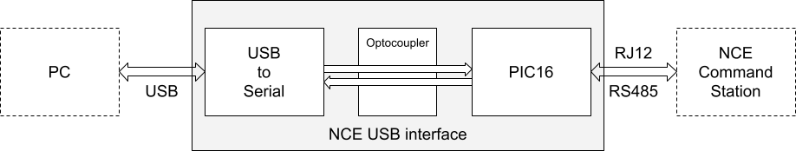
The PC would typically run JMRI or RocRail and communicate with the board using a serial port. The USB connection is nothing more than a basic serial TTY in this case. On the board the PIC16 is the microcontroller that interprets the serial commands and communicates with the command station.
One thing to realize is that this board is nothing more than a controller without a screen and without a keypad. Think of it as an NCE ProCab controlled by a computer instead of you. The computer sends commands following the NCE ops/command protocol (PDF link).
What we want is obviously use this from the Arduino. One option is to use the USB port found on most Arduino, which is often also an USB to serial converter. That's a bit ironic since the Arduino uses a serial port with a CP2102 to convert that to USB, received by the NCE USB card over USB, and that card's CP2102 is transforming back the signal to serial for the PIC16 microcontroller.
The other option, which I used, is to get rid of the middle man, in this case the USB: connect the serial port from the NCE USB card directly to one of the serial ports of the Arduino. The best place to do that is by soldering 2 wires on the USB side of the optocoupler -- the small white chip in the middle of the card. By taking the serial signals on the optocoupler rather than directly on the PIC16, we benefit from isolating the Arduino from the NCE bus.
Our schema now looks like this:
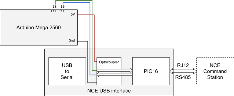
Rather than solder wires directly to the optocoupler going to the Arduino, I drilled 4 small holes in the board and glued a 4-pin header. The RX/TX are soldered to the D213 optocoupler and the Gnd and 5V pins are soldered to the large condenser visible nearby:
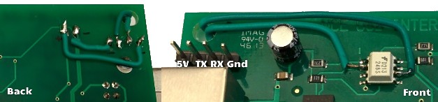
Given the pinout of the D213 optocoupler (PDF), here's how this is all connected:
- D213 pin 2 ⇒ TX header pin ⇒ Mega TX1 pin 18
- D213 pin 6 ⇒ RX header pin ⇒ Mega RX1 pin 19
Note that the optocoupler can be powered just as well using 3.3V or 5V. And that's on the isolated side, so there's no mixup with whatever power comes from the RS485 bus (which I think is 12V anyway). So once I have my small hacked board, I can safely plug it on a Raspberry Pi, a DigiX, a Due, or any regular 5V Arduino. And since I did not cut the traces to the CP2102, I can still connect it using a regular USB cable (just don't try to use the 4-pin header at the same time!)
Below I explain how to use this, and how to debug it.
NCE Protocol
The NCE protocol is a fairly simple serial binary protocol: send a few bytes for a command, receive a few bytes in response, rinse and repeat.
The commands are described in detail in this NCE documentation (PDF download of NCE USB V7).
In my case the only commands I need are:
- 0xAA to read the software version in the PIC16. I'm not currently using it but I could use it as a comm test, and also to make sure I'm talking to the right kind of board.
- 0xA2 to control a locomotive: address, operation and parameters.
- I only need a handful of operations: 03 to send a reverse 128 speed, 04 for a forward 128 speed, 05 for estop reverse, 06 for e-stop forward and 07-09 for controlling functions F0..F12.
- 0xAD to control accessories: address, operation, parameter.
- Operation 3 sets the accessory in normal/on and op 4 sets it reverse/off.
- 0x8A and 0x9B return the status of an AIU card to read sensor data (0x8A gives both the current state and a delta change whereas 0x9B only gives the current state).
The packet encodes the DCC engine address on 2 bytes, MSB first with 0xC0 to indicate it's a long address, e.g. engine 0113 is 0xC0 0x71. To make it move forward at speed 10, send A2 C0 71 04 10 and read one byte of response, in this case ! (0x21) indicating the command was interpreted correctly.
Note that commands to set the function states operate on 4 or 5 bits at once, so for example operation 7 will set all of F0, F1, F2, F3 and F4 at the same time. Interestingly that's exactly how a ProCab controller behaves.
Anecdote: the protocol is so simple that it's also trivial to implement it as a server, for example if you happen to have your own Arduino that needs to send sensor data to JMRI. Instead of inventing a new protocol, have the Arduino behave using that protocol and configure JMRI to use either a serial or a network socket to talk to the Arduino. That's exactly what I do in the Translate project.
Here's an extract of the Arduino sketch with some helper methods I wrote to use the protocol, and to be exact there's nothing here except sending data on a typical Arduino serial port. blink() is a small helper method that blinks the led on the arduino for debugging, omit it if you don't have your own method.
#define LOCO 113 // Alco S-2 #define LOCO_H (0xC0 + (LOCO >> 8)) #define LOCO_L (LOCO & 0xFF)
void setup() { Serial1.begin(9600 /*SERIAL_8N1*/); }
// Send an A2 command (move forward, backward, stop, control F-functions, see doc). void _cmd_loco_A2(int op, int data) { cmd_buf[0] = 0xA2; cmd_buf[1] = LOCO_H; cmd_buf[2] = LOCO_L; cmd_buf[3] = op; cmd_buf[4] = data; Serial1.write(cmd_buf, 5); blink();
// A2 command replies with 1 byte: ! for OK, or 1 if address is incorrect lcd.setCursor(19, 1); if (Serial1.available()) { char c = Serial1.read(); lcd.print(c); } blink(); }
// Turn the engine light on/off void cmd_light(int light_state) { light_state = (light_state == 1 ? 0x10 : 0); _cmd_loco_A2(0x07, light_state); }
// Move engine forward (> 0) or backward (< 0) or stop it (== 0) void cmd_move(int speed) { if (speed < 0) { _cmd_loco_A2(0x01, -speed); } else { _cmd_loco_A2(0x02, speed); } }
// send an emergency stop void cmd_estop() { _cmd_loco_A2(0x06, 0); }
// Set speed steps to 28 or 128. I think default is 128. I don't really use it. void cmd_set_speed_mode(int speed_28_or_128) { cmd_buf[0] = 0x8D; cmd_buf[1] = LOCO_H; cmd_buf[2] = LOCO_L; cmd_buf[3] = speed_28_or_128 == 28 ? 2 : 3; Serial1.write(cmd_buf, 4); blink();
// 8D replies with 2 bytes: ! (ok) or 1 (invalid addr) or 3 (invalid data) + speed mode 0..3 if (Serial1.available()) { Serial1.read(); blink(); Serial1.read(); } blink(); } |
Xminilab
In the introduction image, there's a second green LCD display on my setup:
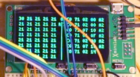
This is an Xmega XMiniLab from Gabotronics. I use it just for debugging. It's a very convenient small board that primarily acts as a basic oscilloscope and can also do voltage meter, but it comes with 2 specific features which are extremely convenient: it can display serial data from either an I²C bus or a regular serial port.
When I started on this project, at first nothing was working, and this immediately showed me I was sending the right bytes but I had RX/TX inverted so that didn't work so well. If you look carefully on the image above you can see a bunch of 0xA2 commands for the NCE.
Connection is simple:
- Xminilab logic pin 2 ⇒ Arduino RX1 ⇒ NCE USB RX pin
- Xminilab logic pin 3 ⇒ Arduino TX1 ⇒ NCE USB TX pin
Then on the Xminilab use the Menu button and configure it to read serial at 9600/8/N/1.
Of course it's just me. Each time I work with serial ports, it happens there's a 50% chance I get RX/TX crossed at some point, a 50% chance I make the same error twice in a row and the rest I get it right the first time. So you probably don't need that kind of stuff. Unless you want one more cool gadget that people wonder what it does.
~~
~~