Layout Automation: |
2015-09
The case for DCC control of Turnouts
If you have a DCC layout, there are many ways to control turnouts via DCC. Typically you might have turnouts controlled by fascia push buttons. DCC accessories allow turnouts to be controlled via a remote controller (e.g. ProCab) or by software such as JMRI or RocRail.
But first, we need to answer the main question: why bother in the first place?
In my case:
- Automated control by software, which means my custom software needs a way to control the turnouts.
- Less wiring. I have no physical control panel on my small toy layout -- it's all done via phone, tablet or computer.
- I can also toggle turnouts using the “Accy” button on the NCE ProCab controller.
Even if you're not in automation, DCC control of turnouts is still interesting. A club for example could have a dispatcher operate the turnouts remotely during an operating session.
If you have existing turnouts, making them controllable via DCC simply means adding an electronic module that will do the control, for example:
- Digitrax offers the DS64 Stationary Decoder to control both twin-coil and slow-motion turnouts (e.g. Tortoise).
- NCE offers the Switch-It for slow-motion machines and the Snap-It or Q-Snap for twin-coil ones.
- EZTrack users can simply use DCC versions of their turnouts (e.g. E-Z Track #6 DCC).
All of these allow for either manual operation or via typical fascia push buttons (more wiring!).
The NCE module is controlled by DCC commands that are sent over the track -- that means it is connected directly to the DCC power bus to receive turnout commands. It can thus be mounted just next to the turnouts to control. No need to have long wires from the turnouts to a control panel. The Digitrax can similarly be connected to the track but also to a LocoNet bus.
One factor is that's all obviously a bit more expensive but probably less than one may think.
For example at the time I wrote this, prices worked that way:
- An E-Z Track DCC turnout is about $30 more than the non-DCC one, so $30 per turnout. That’s expensive..
- The NCE Switch-It controls 2 slow-motion turnouts for $30, so $15 per turnout.
- The NCE Switch-It 8 controls up to 8 slow-motion turnouts for $70, so $8.75 per turnout.
- The NCE Snap-It controls one twin-coil turnout for $20.
- The NCE Q-Snap controls 4 twin-coil turnouts for $70, so $17.50 per turnout.
- The Digitrax DS64 controls up to 4 slow-motion or 4 twin-coil turnouts for $60, so $15 per turnout.
When dealing with Tortoise motors, another option is the Hare or Wabbit from DCC Specialties that have more bells and whistles. This list is not exhaustive.
Track Power vs Separate Power Supply
One interesting thing for twin-coil turnouts: twin-coils need a sudden flow of current to switch. Electronics modules as those listed above can draw that power from either the DCC power bus or from an auxiliary bus (typically a secondary AC or DC power supply).
Let's take a concrete example: the NCE Q-Snap has a 2-pin connector to connect to the DCC power bus. It also has a barrel plug to provide it with DC power. There's a small interruptor in the board to determine if power comes from the power bus or from the DC plug. The commands always come from the DCC bus.
How do you choose which one to use?
These modules can draw a small amount of power from the track, accumulate it in capacitors and use this for snapping the coils. This way there's no need to have a separate DC or AC accessory bus for the turnouts -- the immediate benefit is one less power supply or bus to maintain. If you have too many modules, they will eventually draw too much power from the DCC bus, but that would probably the case of a large layout that would require additional DCC boosters.
The drawback is that an engine shorting the DCC power bus will also render the turnouts inoperative on that block (let's assume block-level short circuit protection is present). And where do we short the most? On turnouts of course. Kind of a catch-22 here… My experience is that it’s always better to power turnouts motors or twin-coils from a power bus that is independent from the DCC power bus.
Arduino versus Off-the-Shelf Solutions
This is an article about controlling turnouts using Arduinos so you might think you can see the choice I’ll make here.
Or maybe not. To jump to the conclusion: using off-the-shelf solutions is most of the time the best way to go.
First rationale: Cost. I listed the cost per turnout of the various NCE / Digitrax choices above.
Second rationale: Time and reliability.
Third rationale: Ease of replacement.
A custom Arduino based solution won't necessarily be much cheaper especially once you factor the time spent working on it. For my own home layout, I use both. I have one QSnap module, one Switch-It module and also my own Arduino-based solution.
I went the custom route for the sake of experimenting. I like software, electronics, and DIY stuff for the sake of experimenting. Spending time figuring out all of this and playing with Arduino and electronics and integrating custom software with more or less compatible one, that's the whole game that I'm looking for. Using off the shelf solutions that work out of the box, that's boring! Yet I do that too because it's easier and I was curious what's available out there.
When I did the automation work on the layout at the Randall Museum, I directly chose NCE and Digitrax solutions. It was a lot easier to budget (x turnouts = x / 4 or x / 8 modules). More importantly it means the day one of them fails, whoever will be in charge of maintenance can purchase the same module and replace it by just wiring it in place. With a custom Arduino solution, it would be required to understand the custom solution and reprogram the Arduino.
As much as I like DIY solutions, they are not always the way to go.
Relays and Twin-Coils
In the discussion below I will be using both Bachmann EZ-Track non-DCC turnouts and Atlas Snap switches as examples. Let's look at how these work and how to control them.
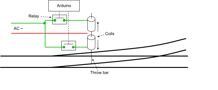
All twin-coil "snap" turnouts work pretty much the same way: two solenoids act as temporary magnets to pull or push a pin that in turn moves the points. In most turnouts I've seen there are 2 coils back-to-back which kind of look like a single one. Both the Atlas Snap and the Bachmann come with a cheap little push button thing: when you push the button, it momentarily powers one of the coils and the magnet moves in either direction to bring the points in normal or reverse.
One drawback from coils is that they overheat. They must not be powered for too long or they will just fry.
Controlling this is trivial: all we need is to have 2 relays that power the coils like the fascia buttons would. The computer or Arduino just needs to activate one of the two relays for a few milliseconds to put the turnout in the desired position.
The only important difference is whether the solenoids are AC or DC. Generally speaking solenoids can be designed for either AC or DC or both. The cheap DC power supplies we use in HO always come with an AC auxiliary bus so one could reasonably assume these twin-coils will work better in AC. My experience with the Bachmann is that using the 16V AC from an accessory power pack worked very reliably, however using the 12V DC power supply I had around didn't work for all of them (their EZ-Track #4 switched properly but not the EZ-Track #6, nor did the Atlas Snap).
But there's another reason we want to care: it depends on the relays we're going to use.
For my first attempt, I used mechanical relays such as these SainSmart 5V DC relays. These work very well yet are quite noisy. The 5V DC indicates what you need to control the board. The relays themselves can handle up to 250V AC or 30V DC in 10A, way more than we need here (actual spec can be found online easily). This board proved problematic as I wanted to use it with a Digistump DigiX, and even when using the 5V pin from that board, the relays would not all switch properly.
Instead I opted to use Solid State Relays, namely these SainSmart 5V SSR. The relays are actually Omron G3MB-202P which supposedly require 5V in input but they work fine when the relays are powered using the 3V pin from a DigiX. These however have an important limitation: the supported load in the spec is only AC. They internally use phototriacs, and a TRIAC, although designed to switch AC can also in theory switch DC, which a small catch: triacs are latching devices. Once triggered, they will only release the output (load) once the current or voltage drops under a certain level. The spec of the G3MB-202P indicates this is 1V. In an AC load, that occurs naturally with the AC cycle. In a DC load, it doesn't, which means triggering the SSR will turn on the load but it will never turn off even when the relay input is released -- and this application would probably fry the coils.
If you need to drive your twin-coals turnouts in DC, you need a different relay, for example the SainSmart 8-CH SSR 5A DC-DC 5V-220V SSR. When you get these boards, look carefully at the specs of the relays if possible.
Arduino and Relays
Since in this demo I had a single turnout, I chose to control the Atlas twin-coil turnout directly using relays rather than using an NCE Snap-It module or using an Atlas DCC control unit.
The operation of a twin-coil turnout is fairly simple: two coils are used as magnets to pull a pin in one direction or another. The pin moves the turnout. The coils must be energized only very briefly (I used 150 ms for example) otherwise they will overheat and burn out. The power for the coils typically comes from an accessory transformer pack. Some twin-coil turnouts can be energized using AC, others DC, others both. The kind I use (either Atlas or Bachmann) seem to work better with 16 V AC.
I choose to use the SainSmart 5V 2-channel solid state relay. Now there are a couple things to mention about it:
- It's a solid state relay, not mechanical, which means it's silent.
- The relays on the board are Omron G3MB-202P which spec can be found here.
Now that last detail is important
The Omron G3MB-202P supposedly requires 5V in input but they work fine when the relays are powered using the 3V pin from a 3V-level Arduino (e.g. all the ARM-based ones or a typical Raspberry Pi).
These however have an important limitation: the supported load in the spec is only AC. They internally use phototriacs, and a TRIAC, although designed to switch AC can also in theory switch DC, which a small catch: triacs are latching devices. Once triggered, they will only release the output (load) once the current or voltage drops under a certain level. The spec of the G3MB-202P indicates this is 1V. In an AC load, that occurs naturally with the AC cycle. In a DC load, it doesn't, which means triggering the SSR will turn on the load but it will never turn off even when the relay input is released -- and in this application that will definitely fry the coils.
So this relay board works for me because I use the 16V AC from an accessory power pack to power the Atlas twin-coils, and these SSR will properly release on AC, but they won't on DC.
If you need to drive your twin-coils turnouts in DC, you need a different relay, for example the SainSmart 8-CH SSR 5A DC-DC 5V-220V SSR. When you get these boards, look carefully at the specs of the relays if possible.
Example 1: Single Turnout
Here's a concrete example, taken from this page. In this case, I'm controlling an Atlas "Snap" Twin-Coil using an Arduino Mega 2560. For a single twin-coil turnout, I only need 2 relays, which is provided by a SainSmart 5V 2-channel solid state relay. Since this Arduino has 5V logic, there is no need for a 3V-5V level shifter (otherwise, you need to either use a level shifter or make sure the relay board still accepts 3V inputs, e.g. that one technically requires a 5V input but it will still work with a 3V input).
Connection is fairly trivial, the relay can be controlled using any of the digital IO pins and the Mega has a ton of them.
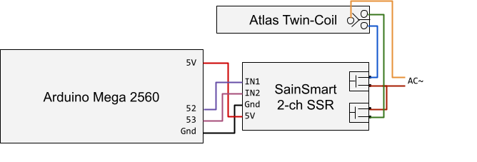
Please note that the Arduino is entirely separated from the AC accessory power. The solid state relays provide opto-isolation.
Controlling the relays is trivial. In this case the relays need to be triggered about 150 milliseconds to trip the twin-coil in the desired position.
#define RELAY1_PIN 52 #define RELAY2_PIN 53
#define RELAY_TIME_MS 150
void setup() { pinMode(RELAY1_PIN, OUTPUT); pinMode(RELAY2_PIN, OUTPUT); digitalWrite(RELAY1_PIN, LOW); digitalWrite(RELAY2_PIN, LOW); }
// Direction: 0=Normal (PIN1), 1=Reverse (PIN2) void set_turnout(int direction) { int pin = direction ? RELAY2_PIN : RELAY1_PIN; digitalWrite(pin, HIGH); delay(RELAY_TIME_MS); digitalWrite(pin, LOW); } |
Example 2: Multiple Turnouts
This is a more beefy version of the previous schema so I'm not repeating the schema part, only showing the end result.
In this case I have a DigiStump DigiX which is an Arduino Due clone.
I had 5 turnouts to control. Since they are twin-coils, 2 relays are needed per turnouts, one for normal and one reverse (a.k.a. thrown state.) I thus need 10 relays and 10 digital outputs. I have 2 Sain-Smart 8-channel relay boards for a total of 16 relays, so technically I could go up to 8 turnouts with the same hardware if I want to expand the layout later.
The Arduino Due, the DigiX and pretty much all the ARM-based Arduino boards run at 3.3V. The relay board technically requires 5V in inputs but in fact it switches nicely using the 3.3V inputs. No need for level shifters.
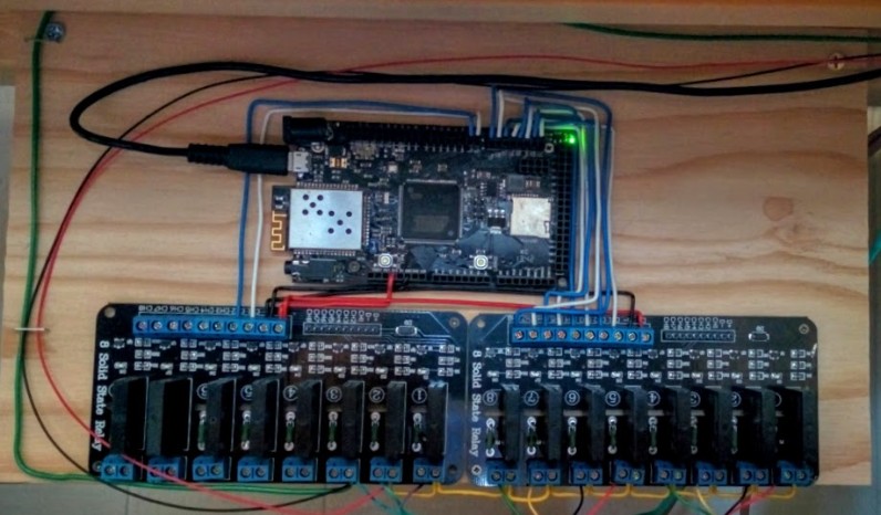
The hardware part is fairly straightforward: 8 digital output pins are used on the arduino, connected to the 8 relay inputs. Relays are grouped in pairs, one to throw the switch in normal and one in reverse.
The relays take 16V AC from a power brick and connect directly to the turnouts, in this case EZ-Track twin-coils which I was reusing, as shown in the schema about for the single turnout example.
One thing that image above shows is the complete lack of DCC power bus. In both examples, I do not control the turnouts from the power bus. This means I can't use my NCE ProCab to switch them. In the single turnout example, the turnout was all controlled by an arduino based on sensor feedback. In this example with the DigiX and the 5 turnouts, the control is done via JMRI -- I have a custom program that emulates an NCE bus (for JMRI) or an SRCP bus (for RocRail), receives the commands from JMRI or RocRail and then sends them over wifi to the DigiX. This way I control them using a tablet and JMRI's WiThrottle or the JMRI web server.
Here's an extract of the Arduino code that is relevant for the relay control (full version here):
// There are 2 relays (one normal, one reversed) per turnout. // There are 2 cards of 8 relays, so we can have a max of 8 relays // and we need 16 output pins: 90-105. #define RELAY_PIN_1 90 #define TURNOUT_N 8 #define RELAY_N (2 * TURNOUT_N) #define RELAY_NORMAL( T) (2 * (T)) #define RELAY_REVERSE(T) ((2 * (T)) + 1)
#define RELAY_TIME_MS 100
#define TURNOUT_NORMAL 'N' #define TURNOUT_REVERSE 'R'
unsigned char _turnouts[TURNOUT_N];
void trip_relay(int);
void setup_relays() { // initialize digital pin 90+ as an output. for (int i = 0; i < RELAY_N; i++) { pinMode(RELAY_PIN_1 + i, OUTPUT); digitalWrite(RELAY_PIN_1 + i, LOW); }
for (int i = 0; i < TURNOUT_N; i++) { _turnouts[i] = TURNOUT_NORMAL; trip_relay(RELAY_NORMAL(i)); } }
void setup() { setup_relays(); // etc }
void trip_relay(int index /* 0..RELAY_N-1 */) { digitalWrite(RELAY_PIN_1 + index, HIGH); delay(RELAY_TIME_MS); digitalWrite(RELAY_PIN_1 + index, LOW); }
void set_turnout(int turnout /* 0..TURNOUT_N-1 */, int direction) { if (_turnouts[turnout] != direction) { trip_relay(direction == TURNOUT_NORMAL ? RELAY_NORMAL(turnout) : RELAY_REVERSE(turnout)); _turnouts[turnout] = direction; } } |
Fairly simple. Enjoy.
~~
~~