The Randall Museum in San Francisco hosts a large HO-scale model railroad. Created by the Golden Gate Model Railroad Club starting in 1961, the layout was donated to the Museum in 2015. Since then I have started automatizing trains running on the layout. I am also the model railroad maintainer. This blog describes various updates on the Randall Museum Model Railroad and I maintain a separate tech blog for all my electronics & software not directly related to Randall.
2018-06-20 - Randall Repairs: Turnouts T370-T371
Category RandallAffected |
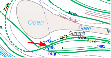
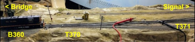
Turnout T370 + T371 (between bridge and signal bridge on Summit). |
Description |
Cold joint at junction between B360 and T370. |
Summary Fix |
Bond wire around B370 and T370 rail (engineer side). |
Description of Issue
Reports of trains stopping on turnouts T370 / T371, between bridge and signal on Summit.
Tried running two engines (GP9 5913, F40PH 506 from automation) and easily encountered the issue.
Measured voltage when engine stops: there was none.
Pushing the rails or the points (even so slightly with the voltmeter) immediately fixed the issue.
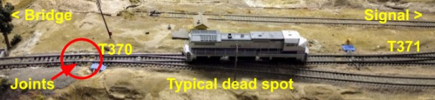
There is a gap between the end of the track of B360 and the T370 turnout. This is an area of the layout that is not properly level and we typically get uncoupling there. The joints (see picture above) are visually crappy. One rail has a rail joiner (fireman side). The other side does not (engineer side). The gap is filled with solder. The rails are fixed in place with hot glue.
Note that the fact the outer rail contact is needed is a clue in itself -- the frog from T370 gets power from the rails after the turnout, but clearly this is not the case as the connection to the rails of B360 seem to be crucial. Further investigation is needed to understand how the power feeds of the junction between T370 and T371. It is likely not powered correctly.
Description of Fix
- Spiked T371 to normal. Didn't fix. However the spike was left in place.
- Spiked T370 to normal. Didn't fix. However the spike was left in place.
- Forced T370 point to proper rail by wiring the frog directly at the terminal block. Didn't fix. Reverted that hack.
Location of spike on T371 (the right most turnout). Although the spike was left in place, it should be eventually removed as this turnout & siding is worth using.
Position of spike on T370. Note that the spike is really hard to see as its on the inside of the rail and matches the color of the tie & road bed at the location.
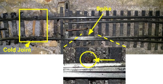
Noticed pushing the outside rail (engineer side) at the joint before T370 would make the engine stop or go -- see rectangle area highlighted above. Interestingly the top view clearly shows the track is poorly aligned at the break.
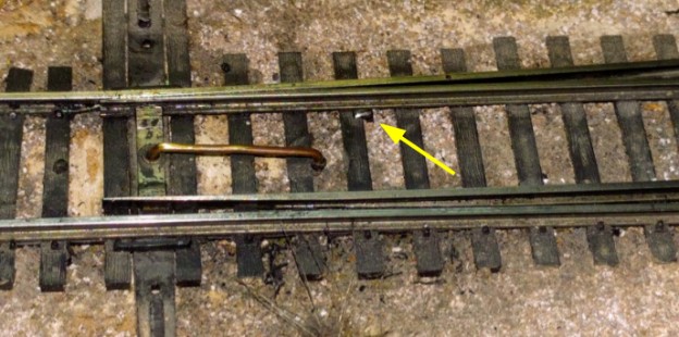
Upon close investigation, found out this joint does not have a rail joiner. Instead there’s a sizeable blob of solder that was stuck between the 2 rails, as shown on picture here:

That is a good cause for a cold joint in a soldered junction as the joint is not flexible and can crack over time.
As I didn’t have a rail joiner and I was running out of time, I opted for a quick and ugly fix which is to install a bond wire across the gap (note the blobs of hot glue under for rails):
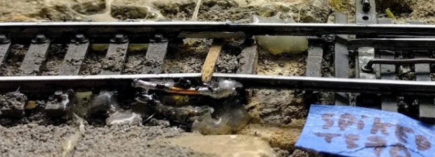
This isn’t a permanent fix. It did seem to hold and did not lose electrical contact when the rail was flexed.
The proper fix, to perform later:
- Remove the bond wire.
- Install a rail joiner.
- Properly solder the rail joiner.
- “Invalidate” T370 by unplugging the switch machine from the white/green turnout wires. This is to prevent it from being accidentally activated. Note that it currently leads to the track B372 where the small station for the Amtrak automation is located, so we don’t really want trains going there for now.
- Unspike T371 as this siding should be cleaned and used eventually.