The Randall Museum in San Francisco hosts a large HO-scale model railroad. Created by the Golden Gate Model Railroad Club starting in 1961, the layout was donated to the Museum in 2015. Since then I have started automatizing trains running on the layout. I am also the model railroad maintainer. This blog describes various updates on the Randall Museum Model Railroad and I maintain a separate tech blog for all my electronics & software not directly related to Randall.
2018-07-01 - RC Filters and DCC signal quality
Category RandallFrom the always excellent Gurries’ web site:
One thing I have experienced a few times at Randall are unresponsive engines. Luckily it is not a very frequent thing and each time I have seen it only on very specific engines. My first TGV unit using a custom LokSound V3.5 had the issue -- when running it after a while on very busy Saturday ops days, it would sometimes cease to reply. I “fixed” the issue by switching to another decoder, a newer LokSound V4.
However I have seen the same issue with other operators’ engines. Very very specific ones, and luckily not that many. I can think of a handful of cases.
A while ago that made me think whether using “snubbers” (RC filters) would be a possible choice, and if yes, where should they be located. Thus the link to Gurries’ web site above.
Unfortunately, when I read his “ideal bus wiring”, it seems to me that the Randall’s wiring is hitting all the wrong spots.
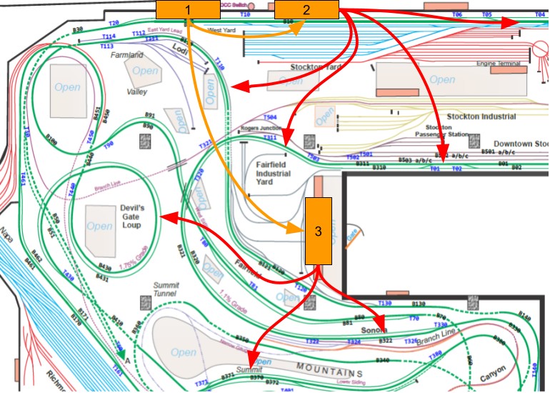
- [1] The four boosters are all located at the same place with an array of circuit breakers creating 10 power districts.
- [2] and [3] are the main concentrated control panels with all the block toggles. They receive power from 4 power districts (2 for the mountain panel, 2 for the valley panel).
- From each panel are bundles of red wires, one per block. Whereas the drawing above has 2 or 3 red wires, consider there are more like 20-30 in each. These bundles of wires first converge then split, each one becomes a red bus wire under the corresponding block on the layout. From that, track feeders are extracted.
- Similarly a black bus wire “accumulates” all the return path towards the panels.
One thing I have yet to understand is whether the black bus wires are also split as one per block or if there’s one per power district or per booster. I think it’s also a mix, with mostly one per block next to the track, all converging to some kind of interconnect terminal. One day I need to spend more time crawling under the layout to figure that one out and write it down.
Compared to good “modern” DCC-friendly bus wiring techniques:
- Twisting the DCC bus is not done here.
- The first part of the bus is a large gauge single pair going from the circuit breakers to the panels.
- The second part of the bus are the black/red bus wires going from the control panels to each block, sometimes together and sometimes following dramatically different paths after the control panels.
- Limiting the non-twisted DCC bus length to 30 ft is not done here. There’s way more wiring than that.
- A random back-of-the-envelope estimation is that going from the DCC boosters / circuit breakers (spot [1]) to the Mountain Panel (spot [3]) is probably 30-40 ft of wiring all by itself, then the DCC wiring goes through the panel itself (2 relays + 1 block toggle + 1 terminal + 1 interconnect bar) before leaving for another 10-30 feet before reaching the blocks’ feed wires.
- Block sensors that I have added are on the Mountain control panel. They are located sort of where the single DCC panel bus splits into separate blocks, which is in placed fairly far away from the where the block powers the track.
- Avoid cross-talk is not done here. Eventually all wires are bundled together in large groups: DCC buses (one per block), turnouts controls, NCE bus, lighting, low-power AC power supplies …
- There’s just too much wiring under this layout. When I talk about “bundles”, I mean literally there are packs of 20-40 wires running together along the support beams under the layout.
What could be done here?
- The single pair of DCC “master” bus going from the circuit breakers to the control panels could be twisted. That would require extracting it from the wire bundles, twisting it, and somehow placing it back.
- The bundles could be broken apart -- DCC wires together, NCE bus at least 1 foot apart from that, and all remaining electrical separated. Extremely hard to do after the fact.
- I already moved the NCE bus apart where it could be separated.
- Going one step further, one thing that could be done but will likely never happen would be to:
- Remove all the block control panels,
- Redefine the power districts by length of maintrack (rather than “geographical” areas in the layout),
- Physically place boosters in each power district, much closer to the track they would power (doubling the number of boosters along the way),
- Rewire new DCC power buses from the boosters to the track feeders (keeping the existing feeders).
- Place the block sensors nearby to the track blocks (just before the feeders).
Doing all that work would probably help a lot, yet without providing any strong guarantee.
It would also be extremely disruptive, preventing any running (both automated and manual) as the work would be accomplished.