The Randall Museum in San Francisco hosts a large HO-scale model railroad. Created by the Golden Gate Model Railroad Club starting in 1961, the layout was donated to the Museum in 2015. Since then I have started automatizing trains running on the layout. I am also the model railroad maintainer. This blog describes various updates on the Randall Museum Model Railroad and I maintain a separate tech blog for all my electronics & software not directly related to Randall.
2018-11-04 - A Mountain of Wires
Category RandallHere’s an example of wiring under the layout. The next picture shows the block power leads out of the Mountain Panel. A bundle of red wires come from the panels, and another bundle of red wires goes to power the blocks on the mountain, and they all meet at this… thing. I’m going to call this an “interconnection board” for a lack of a better term:
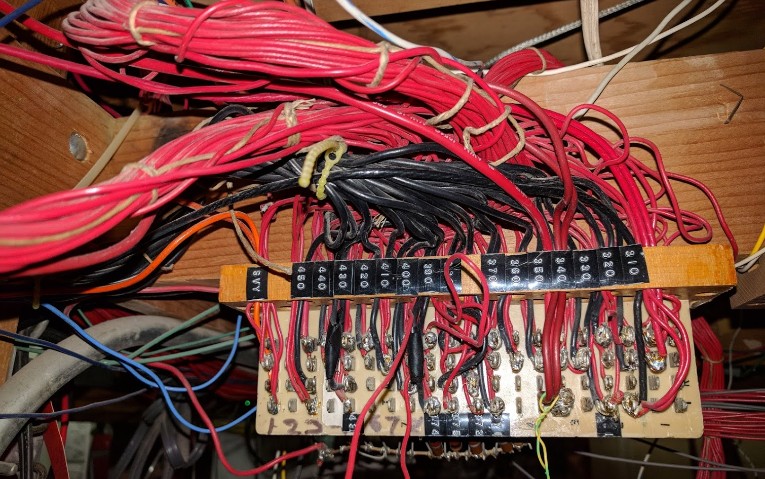
The picture above doesn’t strike me as the best job ever. Now that would not seem too odd, except there are two issues here: first, one of the bundles of red wires just goes nowhere on the ground nearby, and second there’s a bundle of black wires coming in the picture. And do I see the black wires connected to the red wires? Yes I see that clearly.
I couldn’t trace where the black wires connect to or from at first, and I got that bundle of black wires mixed up with the one I’ll be talking about below. One thing is for sure: one should not judge the wires by their color too quickly. The fact these are black vs red does not mean they are both -/+ parts of the DC / DCC bus. They could all be the neutral or the hot of the bus, no matter what their color is.
Here’s the back of the interconnection board, and I have no idea why I am looking at a bunch of 1kΩ resistors:
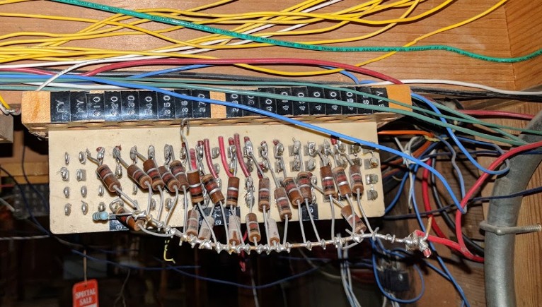
I obviously have a theory of why this is setup that way. I need to crawl again the layout and trace a few more bundles of wires before being sure.
Speaking of bundles of wires:
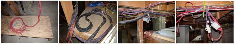
On the left above is one of these bundles of red wires from that interconnection board above. It just wraps around and has been cut. The whole interconnect board is such a mess that I’m afraid of even trying to remove these obviously unused wires.
Next picture shows the bundles of black wires. I traced the bundle going all the way to the back room of the layout -- we’re talking 40-50 feet away, then connect to a bundle of purple wires which go back in the reverse direction -- along the bundle of black wires for a while, except from time to time they split off and end up connecting to some red wires (but not the ones from above). Tracing those red wires ended up fruitless on several occasions. So what does all that stuff do exactly?
Update from 2018-11-06, from a discussion with Mr. Perry:
“Well, those resistor are so old they could also be 10kΩ… [...] it predates my work on the layout… but I think I do know what they are for.
The train detection system on the layout in DC days used the venerable Twin T track detectors powered, I think, with a 27V subsidiary supply. [...] The Twin T system used a current detector circuit much like the attachment here so the detector would register track current being drawn with a train in section. The only problem with it was that a stationary train in DC does not draw current so a standing voltage bias was applied to each block on the rail on one side through a bias resistor and the detector lurked in the return rail. That meant a stationary train would always register.
The attached drawing here shows the bias being applied through a 2.2K resistor but, as the GGMRC layout was so large I think they used 27V and a 10K resistor… so those resistors you see attached to each block cable are the old bias resistors.”
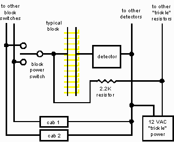
Oh look at that, I know that drawing. It’s from this excellent NMRA clinic on the subject of block detection:
http://www.gatewaynmra.org/1997/easy-block-detection-2-color-signals-detection-systems-circuits/
So should we keep the resistor?
“[There] is no reason for [them] in DCC and they could all be removed.”
What about these bundles of cables going to the back room and then back to the Mountain division?
“Quite probably those are the return wires to the Twin T detectors and back to the controller. There should also be a similar arrangement for the Valley of course.”