The Randall Museum in San Francisco hosts a large HO-scale model railroad. Created by the Golden Gate Model Railroad Club starting in 1961, the layout was donated to the Museum in 2015. Since then I have started automatizing trains running on the layout. I am also the model railroad maintainer. This blog describes various updates on the Randall Museum Model Railroad and I maintain a separate tech blog for all my electronics & software not directly related to Randall.
2018-11-11 - Stockton Passenger Station Power, Continued
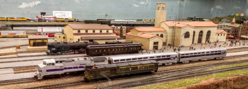
Category RandallThe Stockton Station is certainly the most visible feature of the layout when visitors walk in the room and approach the middle of the room.
Last week, I wondered “Where does the power from the Stockton Passenger Station come from?”
Resolving that question took a full week, and was accomplished with the help of Mr. Perry who provided his extremely well detailed original schematics of the power routing to the station, which I turned into these schematics:
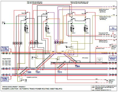
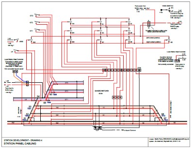
For a full size readable version of the schematics, please refer to the “SD+DOW” PDF in the resources pages under the schematics section.
Not only did I get the schematics, but I got to ask how the station was designed to be used. I also verified all the schematics and they still match the current layout electrical installation. Nothing significant had been changed, which is good. I redrew all the schematics using colors to identify things such as blocks & common rails continuity. I also annotated them with which DCC booster / circuit-breaker is connected today, and I added notes to help me locate the relays under the layout.
DC operation & design, as explained by Mr. Perry:
- The station is connected to the East (right side) to the mainline, or the stockton yard, or the roundhouse lead. This is the Approach East block.
- The station is connected to the West (left side) to the mainline at block B311 or the branchline via T504. This is the Approach West block.
- Tracks 1, 2, and 3 for the station are composed of 3 segments (West, Central, and East), each with a power selector: left for West approach, middle for off, and right for East approach.
- Power for West comes from:
- Block B321 if T311 is thrown to connect the station to the mainline track #2.
- Block B320 if T311 and B320 are thrown to connect the station to the mainline track #1.
- Branchline if T504 is thrown to connect the station to the branchline.
- Otherwise from a local West Power Controller (no such power supply was installed though).
- Power for East comes from:
- Block B10 when T04 is thrown, connecting the station to mainline track #1 in front of the yard.
- Block B21 when T04 and T05 are thrown, connecting the station to mainline track #2 in front of the yard.
- The Roundhouse Cab power when T604 is thrown, connecting the station to the Roundhouse Lead.
- Or the Stockton Yard power when neither of these turnouts are thrown and the STN/YD switch is set to YD.
- Or to a local East Power Controller when the STN/YD switch is set to STN, or T03 was thrown. No such power supply was installed on the layout, though, so in this case the station would have no power.
- The 3 spurs at the top have their own power through the West Power Controller.
When the layout was powered in DCC, DCC was injected on the “right” side (East approach) and would indirectly come from either the mainline, the roundhouse or the stockton yard (by default). That’s the reason why each block power selector has a “yellow dot” on the right, to indicate this was the default setup. The inconvenience of this scheme is that the station would lose power when T03 was thrown, or the STN/YD switch was thrown to STN side.