The Randall Museum in San Francisco hosts a large HO-scale model railroad. Created by the Golden Gate Model Railroad Club starting in 1961, the layout was donated to the Museum in 2015. Since then I have started automatizing trains running on the layout. I am also the model railroad maintainer. This blog describes various updates on the Randall Museum Model Railroad and I maintain a separate tech blog for all my electronics & software not directly related to Randall.
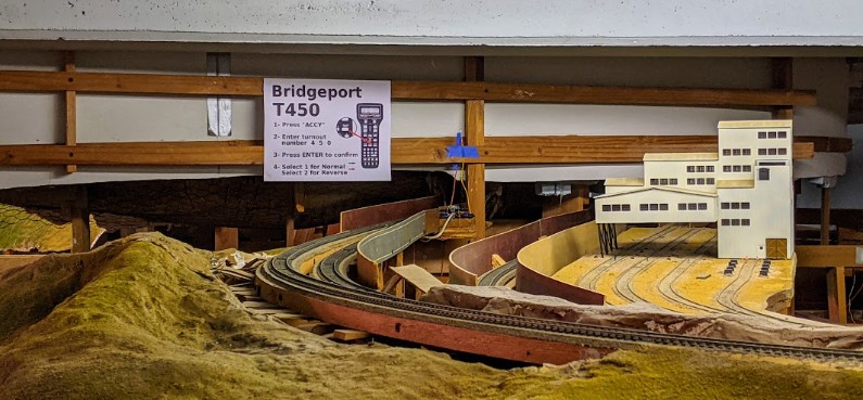
2020-12-06 - DCC control for Bridgeport Turnout
Category RandallWe now have DCC control for the Bridgeport turnout, with some caveat:
For this I used a Digitrax DS64 to control the Fulgurex slow-motion motor.
As I said… “with some caveats”:
The main issue is that the Fulgurex fails to throw the point in reverse. Measuring the DS64 output, I get 12 V for the Normal position, but only 3.8 V when throwing in reverse. Consequently the motor has not enough power to throw the bar unless I give it a little manual push. I have seen that behavior with other Fulgurex motors on the Napa turnouts. This was solved by replacing the Fulgurex motor from the stock we have. I might try to lubricate this one first to see what happens, since after all it has not worked for 2-3 years at least. I don’t think it’s due to dust, as it works fine in the forward direction.
The reality is that the Digitrax DS64 is barely adequate to drive a Fulgurex motor. They just consume too many amps, and the DS64 output is not symmetrical. One would think it would be, yet it clearly is not. The DS64 outputs have better impedance in one direction than the other, thus incurring some kind of voltage drop as soon as the slow-motion motor consumes too much current -- and to be fair the Fulgurex is borderline out of specs IIRC.
The solution is to replace the Fulgurex motor by another one that works better (as I did for Napa), or to replace the DS64 by an NCE Switch-8 and an NCE Relay Board (as I did for Sonora T330) as these work fine with a Fulgurex.
An important technical detail is that the Digitrak DS64 TRK A/B (input power) comes from the Mountain Panel 2. The turnout T450 being controlled is in the Mountain 1 district. This is done on purpose -- if a train derails on that turnout, it will trip off the breaker for Mountain 1, and thus the DS64 will still have power (from Mountain 2) to be able to throw the T450 turnout. Conversely, if a train is derailed on the mountain and trips the Mountain 2 district, the Bridgeport turnout will not be functional. (That is actually a flaw in the DS64, namely that their DC barrel input is electrically linked to the TRK A/B terminals so one cannot use the TRK terminals just for the DCC signal yet provide a better DC input through the barrel connector; this is possible on the NCE Switch-8 which is better designed on that regard).
I also temporary mounted a LED to indicate when the turnout is thrown -- note this is temporary, I was exploring where to place the LED and I am not satisfied with the current placement:
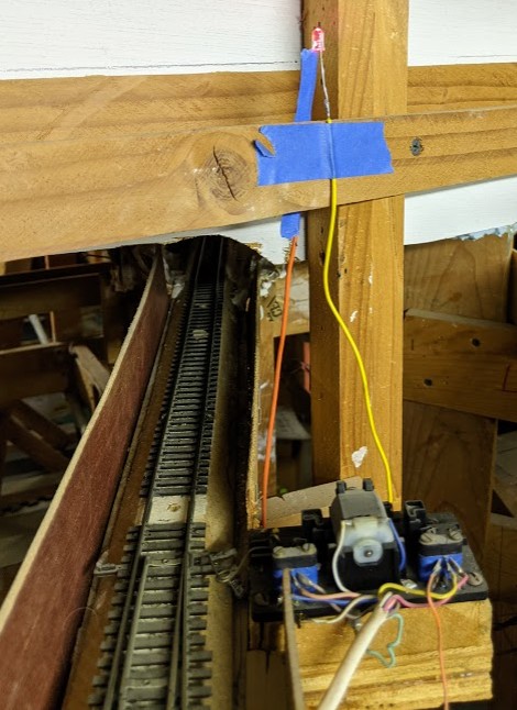
As with the Napa approach, I am using a single red LED to indicate when the turnout is left in reverse -- there is no green LED in normal position. Here I have the LED with a 2.2k Ω resistor, directly driven off the frog and the “A” rail. It’s rather crude (LED reverse voltage breakdown, anyone?) yet it surprisingly works nicely.
Placement is not adequate though, so I’ll try a few options. Also the LED needs to point towards the operators for more visibility, not towards the ceiling. As I have done in other places, I will likely mount the LED in a terminal block instead of soldering it; it’s easier to change that way.
Finally that wiring in the panel is increasingly becoming a huge mess, and I don’t like it:
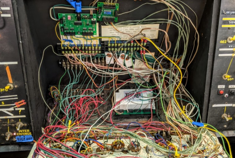
It’s going to be some undertaking to make it look clean, and it’s made more complicated by the fact there are 4 different bundles of wires in there -- the original block lights system, the original DC/DCC toggles wires, the wires for the Switch-8 with fascia toggle control, and the latest wires for the DS64. I have some idea on how to make it all look clean except once I draw them on paper I realize my ideal setup would not fit in the allocated space.