The Randall Museum in San Francisco hosts a large HO-scale model railroad. Created by the Golden Gate Model Railroad Club starting in 1961, the layout was donated to the Museum in 2015. Since then I have started automatizing trains running on the layout. I am also the model railroad maintainer. This blog describes various updates on the Randall Museum Model Railroad and I maintain a separate tech blog for all my electronics & software not directly related to Randall.
2020-12-22 - A Convention for Wiring Tortoise Switch Machines
Category RandallHow are Tortoise wired on the layout? A lot of the existing mainline turnouts use a terminal block. This makes it easier to prepare the turnout machine at a bench, and then install it in place without soldering. So let’s replicate this. What is the current wiring pattern?
Some examples:
Tortoise at Mainline T110:
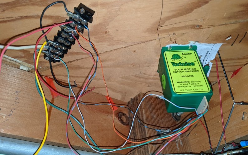
Terminal block = 8 positions (1 == right most).
- Terminal 1 / Green Turnout Control ⇒ Tortoise 8.
- Terminal 2 / White Turnout Control ⇒ Tortoise 1.
- Terminal 3 / Yellow = not connected.
- Terminal 4 / empty.
- Terminal 5 / empty.
- Terminal 6 / Red = DCC bus red or from rail A ⇒ Tortoise 3.
- Terminal 7 / Orange = to frog ⇐ Tortoise 4.
- Terminal 8 / Black = DCC bus black or rail B ⇒ Tortoise 2.
To reverse the switch, it’s possible to invert the green/white either on the bus side or the tortoise side. An 8-position terminal block makes sense to be able to use both switch contacts. In practice, I rarely see that being used.
On the Fulgurex at T450 Bridgeport, the conventions are different.
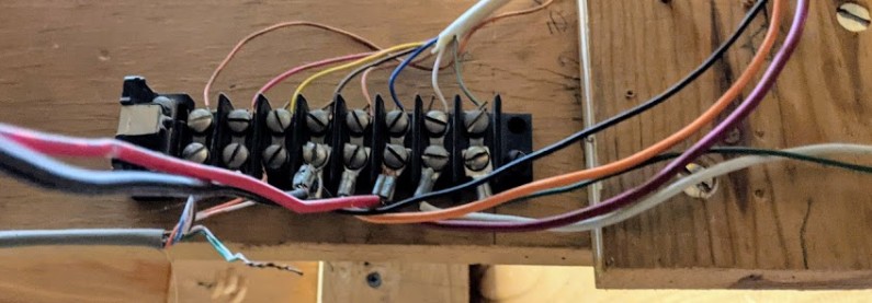
Terminal block = 8 positions (1 == right most).
- Terminal 1 / Green Turnout Control ⇒ Turnout control. ⇒ green
- Terminal 2 / White Turnout Control ⇒ Turnout control. ⇒ white
- Terminal 3 / Red = DCC bus red or from rail A. ⇒ blue
- Terminal 4 / Orange ⇐ Switched by Fulgurex from 3-5 ⇐ orange
- Terminal 5 / Black = DCC bus black or rail B. ⇒ gray
- Terminal 6 / Other switch out ⇐ yellow
- Terminal 7 / Other switch in ⇒ red
- Terminal 8 / Other switch in ⇒ orange
Interestingly I realize the “other switch” for T450 is wired yet I have no idea what to… I should follow that cable some time.
Pictures from Napa T150 / T151 show a similar setup, with variations.
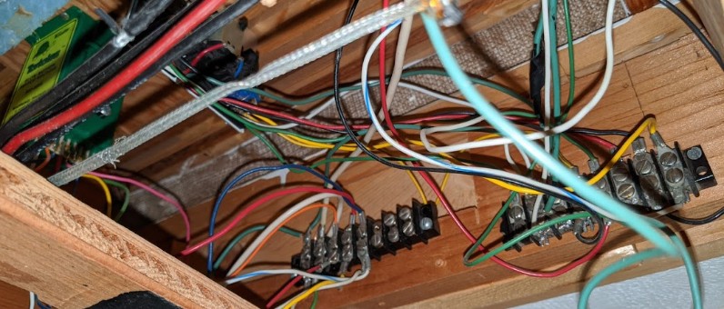
The same green / white / red / orange / black can be seen, although on a left-to-right variation (basically rotated 180 degrees). On one Tortoise, the 2nd switch is not wired. On an older Fulgurex, it is wired to the switch but not used on the terminal. On the cross-over side, there’s a 6-position terminal block instead for both switched parts, whereas the green / white control wires go directly to the main terminal block.
Thus my convention is going to use a 5-position terminal block: https://amzn.to/37EWkOj
These have 7.1 mm of clearance for spade crimp fork connectors.
I noticed I have 2 sizes of spade crimp fork connectors at home, based on their “stud” size (the internal part of the fork in mm): “4” which are 6.4 mm wide, and “5” which are 8.1 mm wide. The larger ones (#5) do not fit in these terminal blocks, however the smaller ones (#4) do fit. I have them both in red (22-16 AWG, or 22-18 AWG depending on which specs I read for what looks like the same product) and blue (16-14 AWG).
The ones I use (http://amzn.to/2etJjYY) do fit.