The Randall Museum in San Francisco hosts a large HO-scale model railroad. Created by the Golden Gate Model Railroad Club starting in 1961, the layout was donated to the Museum in 2015. Since then I have started automatizing trains running on the layout. I am also the model railroad maintainer. This blog describes various updates on the Randall Museum Model Railroad and I maintain a separate tech blog for all my electronics & software not directly related to Randall.
2020-12-21 - An Update on the Lodi Maintenance
Category RandallThe last couple visits at the museum were to deal with Lodi. The original premise was extremely simple as elaborated in the previous post about Lodi: provide access to the block B905 leading from Lodi to Fairfield for switching purposes. Jim indicated he tried to use it only to find it had no power. Since this block is powered off Fairfield, which is currently powered off, the trivial fix was to cut the block in two by creating a gap and then power it from the Lodi side.
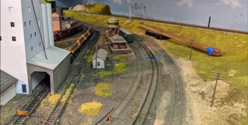
Lodi on the left, mainline (the dark rails in the middle), and the Fairfield B905 block on the right.
That did not go smoothly. In fact so far it has gone absolutely nowhere except to create more work for what was supposed to be a trivial thing. Oh well. C’est la vie.
After locating the power feeder in the B905 block, I simply cut both rails using a small hand saw a couple inches before.
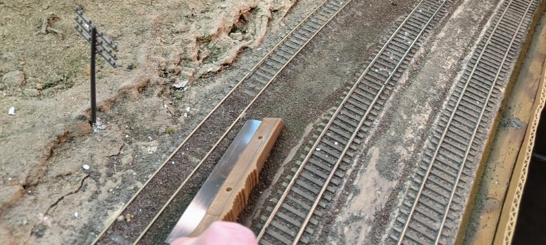
I cut both rails. The layout uses a common rail from its DC heritage, and we need proper DCC booster separation.
That leaves half the block powered from Fairfield, which I do hope to be able to restore one day, and then leaves the other half currently totally unpowered. I’ll need to solder new power feeders later and connect them yet that is secondary since the purpose right now is just to spot cars on that and treat it as a spur. Jim can use some buffer cars to make sure the engines don’t reach the unpowered section.
I switched my focus to the turnout itself. Jim said he had used it, so all I had to do is verify it was throwing properly and make sure the frog was properly wired. Should be trivial.
There came a neat surprise:
The Lodi control panel.
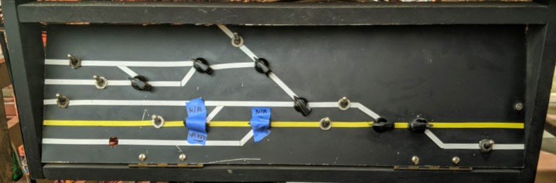
The switch I want to control is the one to the right with the blue tape labelled N/A on top. Yellow is the mainline, and the bottom track is B905 leading to Fairfield. I put that piece of tape there 3 or 4 years ago when I was trying to identify what worked or not on the layout.
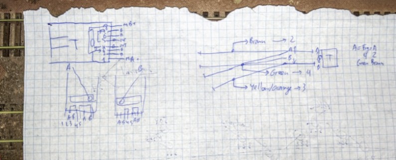
At first I couldn’t remember why I did that… and a quick examination revealed that: 1/ the turnout knob has one side unsoldered. I don’t know why. That would be easy to solder back. But 2/ the wires lead to a terminal block that is… not used. And 3/ the turnout’s switch machine is one of the older twin-coil types that is directly connected to the Fairfield panel across the room, not this panel at all!
That explains why I labeled that turnout as “N/A”. I had good reasons.
The back of the panel with the two green wires not even connected to the turnout knobs:
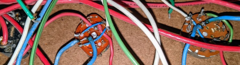
The switch machine is one of the older twin-coils kinds, and all the connections are fairly loose (dry solder):
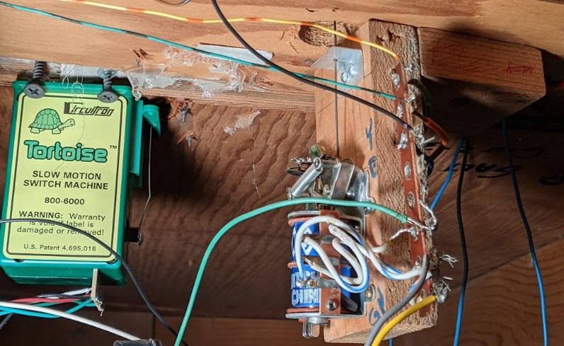
OK so now plan B is to verify we can still use that twin-coil. There are a lot of them still on the layout, and the nice folks from the GGMRC had started replacing them because they all fail with interesting and consistent failure modes.
Throwing the switch manually revealed that it would not power the frog correctly. This is a fairly common failure mode in these twin-coils where the switch at the top that powers the frog from either rail A or B fails. In this case one of the blades lost its “springiness” and wasn’t making proper contact. When it does, there’s a high resistivity -- which can often be addressed by filing the metal points and using an adequate amount of CRC 2-26 for better contact. So I did try to address both of these, and got some kind of proper frog conductivity in the reverse position. Not ideal but enough to make it work.
I also figured one quick way to make this work would be to use an NCE Q-Snap that I had around to control the twin-coil from the DCC via the NCE PowerCabs. A not-so-quick test revealed the twin-coil would only throw in one direction and never in the reverse one, which is yet another of their typical failure modes.
OK fine, now I’m at plan C. Replace the twin-coil. I could replace it by another surplus twin-coil that may or may not work or may fail soon later. Or I could replace it with a Tortoise. Oh but I don’t have any left, since one nice person from GGMRC took the last box on their way out. I’ll need to order some. In the meantime, plan D… it turns out I do have one “spare” Tortoise switch-machine. It was left around because it was not complete. It’s missing its fulcrum, but that’s OK as I found one layout around in a pile of discarded scrap. And it lacks the torsion bar, but that’s fine as I also found some leftovers I can reuse. I do need to find a screw to fix the torsion bar; I couldn’t find any suitable in the organized mess that is the “track cabinet” from the layout backroom, but I should be able to find one at home. I’m also missing the mounting template yet I found some in the track cabinet that I can use. Finally I need mounting screws and I located some that seem appropriate. So that’s plan D. Rebuild a functional Tortoise from leftover bits, install it, and wire it.
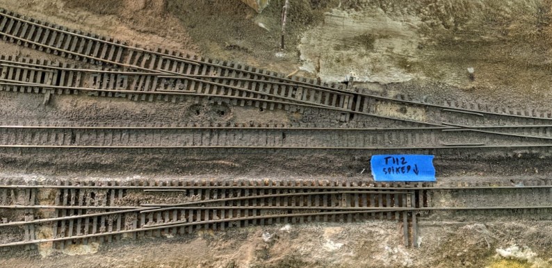
In the meantime the turnout is spiked as there’s no motor for the point, and the frog is hard-wired for mainline usage till I reinstall a proper turnout motor.
Lodi sidings at the top. Mainline at the bottom, branching towards B905 for Fairfield at the bottom left.
To be continued. Next year.