The Randall Museum in San Francisco hosts a large HO-scale model railroad. Created by the Golden Gate Model Railroad Club starting in 1961, the layout was donated to the Museum in 2015. Since then I have started automatizing trains running on the layout. I am also the model railroad maintainer. This blog describes various updates on the Randall Museum Model Railroad and I maintain a separate tech blog for all my electronics & software not directly related to Randall.
2020-12-26 - Grade Crossing Pro/2
Category RandallToday on the bench we have a Logic Rail Technologies Grade Crossing Pro/2:
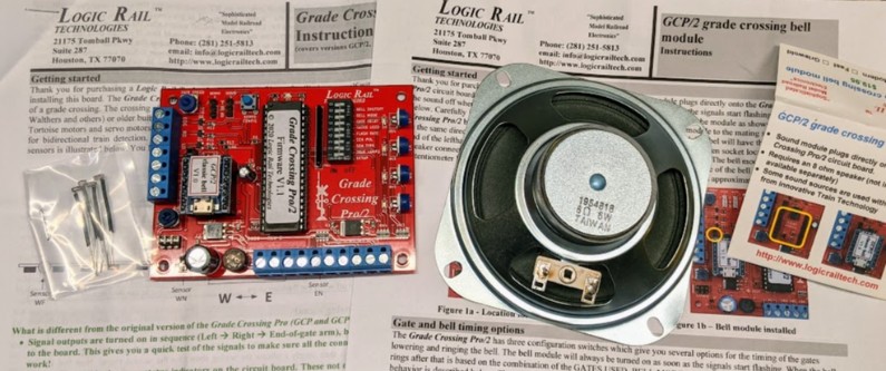
That is going to replace the module that I had previously installed on the layout back in 2015.
Experiment on the bench first, to check everything out:
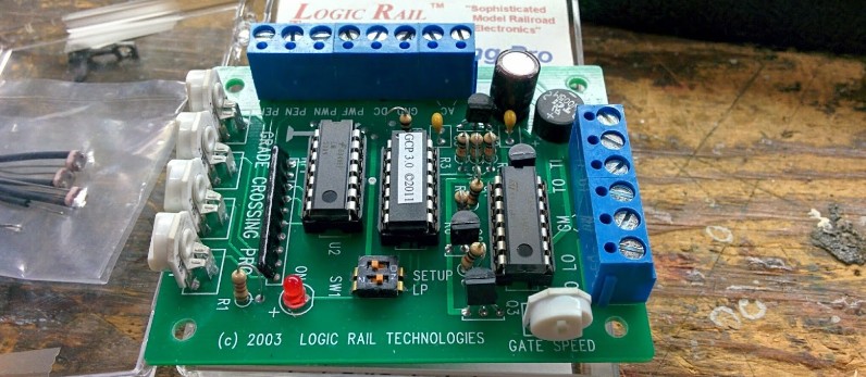
This is a newer version of the previous Grade Crossing Pro. For comparison, here’s a picture I took back in March 2015 of the brand new one I had installed back then (that’s the module that was unceremoniously removed):
The new design is pretty neat. The new one uses a different CPU -- can’t really tell which one and I don’t want to remove the sticker. DIP-40 form factor; if I had to take a guess I’d say any DIP-40 variant of the ATmega AVR family from the ATmega16 up to ATmega644 (the ATmega number is the flash size, and a DIP-40 form factor gives about 32 I/O pins).
The new sound module is handled using a little daughter card, whereas the older setup was a fully separate sound board driven by the main board. The new sound module is a JQ6500 board -- a generic MP3 player with 2 MB sample size, designed to be used with Arduino-like ease.
The new board comes in two flavors: either classic photoresistors, or infrared LEDs. There are pros and cons to each. The photoresistors have the known issue that they need to be adjusted to ambient light, so they don’t work well in a day/night setup, and this board does not use a fifth photoresistor to measure ambient lighting. As for install, photoresistors are trivial since they just need one little drill hole that happens to neatly match the spacing between HO-sized ties. Infrared LEDs use the typical “bouncing” proximity: one LED emits and one receives. Two holes are required between ties, and the doc explains in detail the ideal install setup (angled, separated by one tie each). They use a bit more power since the four IR LEDs need to be powered all the time. This can still be sensitive to overhead lighting conditions, however it is guaranteed to be able to work in a dark night scene. Some train’s plastic bounce the IR signal better than others.
In our case, since the layout previously had the setup with photoresistors, I went for that option since I plan on reusing the existing photoresistor spots. Four photoresistors are provided, with a heat-shrink tube on one lead. They have no marking. Testing one, I got about 1.1 MΩ in the dark and about 440 Ω with the bench LED lighting.
Powering the board: Documentation calls for 7-14 V in either AC or DC. Last time I used a Bachmann HO power supply and I know it’s still there under the layout, so I’ll likely reuse it too. It has both an AC output (~16 V) and the “DC” controllable output… I use the DC one, set it, then tape the knob to make sure no-one else changes it. To get started I’ll use a 9 V AC transformer I have around.
Looking at the new board, their 7-14 V recommendation makes sense:
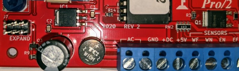
Just to the left of the AC terminal is a bridge rectifier. And just above that is a 7805 (IC1), a typical 5 V fixed voltage regulator. Marking indicates an On semi 7805CG RQL35, aka MC7805CDTRKG in Farnell or DigiKey. Nominally, input must be 2 V above output thus 7 V min per specs.
Wiring for photocells:
- WF = West Far / WN = West Near / EN = East Near / EF = East Far.
- Photocell locations will reuse previous setup:
- WF = Just after the T130 turnout to Fairfield.
- WN = About ~1 ft to the left of the crossing
- EN = About ~1 ft to the right of the crossing
- EF = Just before the level crossing after the Fairfield station.
- Has the previous photocell wiring been removed too?
- Mounting photocells from the top of the layout.
- Hopefully existing holes are the proper size and they won’t fall through.
- If not, hold them underneath using tape.
- If holes are “just the right size”, a common trick is to use a drop of white glue or silicone caulk to hold them in place, yet be easy to break later.
- Do I want to use 2-position terminals? (which I don’t have anyway… ⇒ I could make-shift some using PCB 2-position screw terminals, which I do have).
- All wiring to the terminal at the bottom of the GCP/2:
- One individual wire to each photocell.
- All photocells to GND
- Suggestion: One wire from GND to closest photocell + then one “bus” GND wire to each photocell.
Speaker connection:
- 8 Ω speaker to the left terminal.
- 2 bottom positions are SPKR.
- There’s a pot under it to adjust volume.
We are wiring SceneMaster Walthers crossing signals.
From the SceneMaster Walthers instructions:
- Cantilever signal 2-lane (Walthers 949-4330):
- 3 wires (1 black, 2 red-black). There are 3 signals with 2 LEDs eachs on the mast/cantilever, thus I’d guess each wire controls one LED.
- Tested: The single black wire is the positive side of the LEDs, and the two red-black ones are the negatives.
- Signal instructions: LEDs rated for 1 V max.
- Signal instructions: Use “One 1000 ohm resistor on the black wire”.
- Crossing flasher (Walthers 949-4333):
- There are 2 masts, with 2 LEDs each. One black and two copper/yellow wire.
- Signal instructions: LEDs rated for 2.3 V max.
- Signal instructions: “Black is the common ground”.
- GCP/2 instructions are to use one resistor per LED instead of a single common one.
- I’ll use 1k Ω resistor, one per output.
- Connects to RO / LO on the left terminal block.
- The other side connects directly to the “DC+” ⇒ the LEDs are connected directly to the DC power supply or to the output of the AC bridge rectifier.
Interesting GCP/2 application note: we can use open-drain detectors such as the NCE BD20. In this case 3 are used: one for WF, one for WN+EN, one for EF. All connect to ground and I’d guess sink current from the W/E output. Which means this could be another Arduino-like component triggering these, as long as they share the same supply. And that terminal at the bottom has a +5 V terminal, which is an output to the on-board 7805 and obviously connected to the VCC middle pin of the GCP/2 CPU. Thus we can power an external Arduino/ESP32-like from this and have it simulate the necessary WF/WN/EN/EF triggers.