The Randall Museum in San Francisco hosts a large HO-scale model railroad. Created by the Golden Gate Model Railroad Club starting in 1961, the layout was donated to the Museum in 2015. Since then I have started automatizing trains running on the layout. I am also the model railroad maintainer. This blog describes various updates on the Randall Museum Model Railroad and I maintain a separate tech blog for all my electronics & software not directly related to Randall.
2020-12-31 - Cleanup & Mystery: Junior Engineer DC Console
Category RandallThe amusing thing working on a mostly-undocumented quinquagenarian layout is that most electrical circuits work in layers. Clearly stuff has been added later, then sometimes retrofit and upgraded, etc. As I found out, trying to remove any innocent-looking obviously unused old piece of equipment can result in a lot of fun. As in “mystery puzzle kind of fun”.
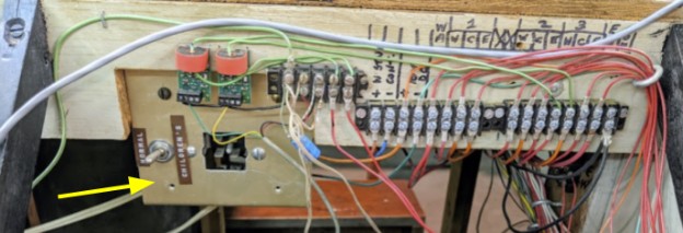
Task of the day: Removing the old plug for the Junior Engineer DC console. This little plate & connector on the left side of the Stockton Passenger station. I’m updating the station panel for a circuit breaker to later add more automation block detection and turnout control. I could use the space. That obsolete plug can go away, since it hasn’t been used in 5 years and it will not be used ever again. How hard can that be?
Doing so totally broke power to Mountain Panel 1. Why?
Looking at the back:
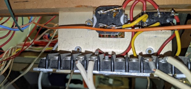
The right side white wires go to the black/red terminal that connect to the Mountain panel:
For these, it’s easy as the bottom black and red wires connect to the relay on the panel which connects directly to the DCC booster / circuit breaker.
That makes the right side white wires the input (from the panel’s DCC).
The “Normal / Children’s” toggle selects power from the right-side of the terminal or from the front plug, and feeds it to the left-side white wires.
That makes the left-side white wires the output.
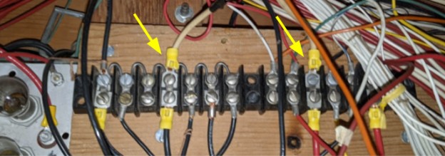
The left side white wires go to this terminal:
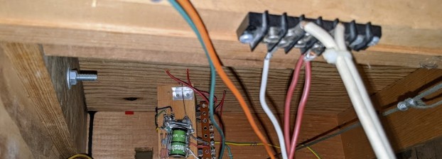
I was not able to trace properly where this one white and two red wires are connected to.
I unplugged the DCC from the Mountain 1 panel and was expecting that terminal to be unpowered. Yet it showed a DCC voltage on it. Huh?
Back of the envelope drawing, from what I understand:
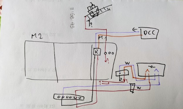
That means:
- Power comes from the DCC boosters via the circuit breaker (10 AWG purple/orange wires).
- Arrives at Mountain Panel 2 to the old DC-DCM-DCC double relay (which I kept in place as a “toggle”).
- Goes out via 10 AWG black/red wires to the terminal under the panels.
- From there goes out to what looks like ordinary household 18 AWG electrical wire to the right-side “input” of the “Children’s” plug/toggle.
- This plug/toggle is a basic DPDT toggle.
- Power goes out via the ordinary household 18 AWG electrical wire going to the 2-position terminal next to it.
- Power goes out via one white cable + 2 red cables (~16 AWG).
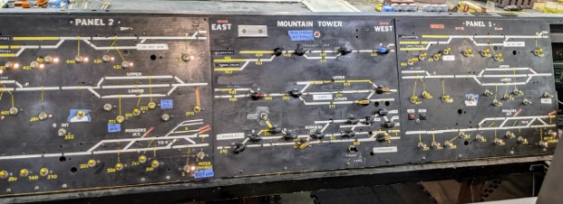
- Somehow that power arrives to the main “source” red wire that powers all the block toggles on the panel.
- From there, I do know that each toggle has an outgoing red wire going to an interconnection board where each blocks from both Panel 1 + Panel 2 is connected together going to yet another red wire going to the actual track block feeder (and yes, that’s a lot of red wires bundles, almost impossible to trace).
- I also know that all the common grounds for all track blocks are connected between both panels using a similar interconnection bus bar, located 15 feet away under the Stockton Yard.
The irony of that convoluted power routing, with a mix & match of large gauge wires connecting to smaller gauge wires, and the extra dozen of feet of wiring used for each block does not escape me, especially when I hear reports of trains power loss in the mountain.