The Randall Museum in San Francisco hosts a large HO-scale model railroad. Created by the Golden Gate Model Railroad Club starting in 1961, the layout was donated to the Museum in 2015. Since then I have started automatizing trains running on the layout. I am also the model railroad maintainer. This blog describes various updates on the Randall Museum Model Railroad and I maintain a separate tech blog for all my electronics & software not directly related to Randall.
2020-12-29 - Power Districts for Fairfield and Stockton Station
Category RandallTime to deal with installing the two new circuit breakers. One for the Fairfield industrial city, and one for the Stockton Station. The former is not powered at all. The latter is powered in a convoluted way from other parts of the layout, and I need it separated to both solve issues and make it suitable for automation. This all needs careful planning to investigate all the possible options.
Location for the breakers. One philosophy is to place the breakers near their usage panel, which makes sense for a walk-around layout design -- the EB1 makes it easy to have a LED on the panel indicating when there’s a short.
The other philosophy is to place all the breakers together, which makes it easy to glance which one is shorting. Since this layout already uses the latter design with all the current breakers together, I’ll stick with it.

Boosters which I have selected for these:
- Booster 2 = P2 Fairfield.
- This booster also covers Lodi, Napa, Valley 2.
- Booster 4 = P4 STK STN.
- This booster also covers Mountain 2, Bridgeport, SIA Roundhouse.
Note that booster selection was made by computing how many trains we typically run in each power district. Booster 1 covers the Stockton Yard which has a lot of activity. Fairfield will have low usage, and can be combined with Booster 2 as Napa / Lodi (low usage). Booster 3 covers the Mountain 1, which is full of up-hill grades and has already enough reports of limited power. Booster 2 covers the Mountain 2 which has mostly down-hill grades; it also covers the SIA which is currently unused, and Bridgeport which has very low activity.
Panels relay: each current panel has a double relay which was used to select between DC, DCM, and DCC power. When converting to all DCC, I left these relays in place, even though they don’t select between anything. The relays are still powered by power from the main layout power toggle. This allows me to isolate a panel just by pulling the relay off, which is very convenient when doing some maintenance -- it’s my crude form of a security lock-out at the panel. I will likely not install such relays here. However power will go to a terminal block so that I can easily unpower each panel.
Power for the Fairfield panel is rather trivial. The panel currently has a power selector to power it from the B130 block (Sultan side), or B110 (Lodi side), or from the yard.
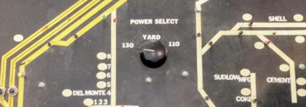
All it takes here is to bypass the power selector and feed directly to the terminal block on the output of that power selector.
Power for the Stockton Station is a lot more complicated. I have a lot more details here; each block can be powered:
- From the “West”: B321 if T311 is thrown, B320 if T311 and T320 are thrown, Branchline if T504 is thrown. Otherwise power comes from an unused West Power Controller terminal.
- From the “East”: B10 if T04 is thrown, B21 if T04 and T05 are thrown, Roundhouse if T604 is thrown; if neither are thrown, the STN/YD toggle takes power from the Stocktown Yard cab, or from the unused East Power Controller terminal.
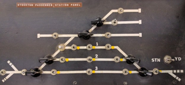
Details can be found on drawing #4 on the Station Schematics, which I recreated based on info provided by Mr. Perry. These details the power routing for each station block.
That complicated power routing made sense when the layout operated in DC: an operator willing to take a train in or out of the station would select a direction -- East towards the yard, or West towards the mountain -- and then the blocks would be directly powered based on the turnouts thrown to get in or out of the yard. That’s necessary since in DC the voltage controls the speed.
For example when a train needs to get out of the station, if we select the “West” position for the station blocks, it leads the train to the mainline B321 block, and thus the routing powers the station block from the B321 block via a complex system of interlocking relays.
In DCC, or more exactly for my automation system, this creates a problem: the computer detects a train position on blocks by looking at which block consumes power. But when blocks are connected together, any train on the linked blocks is detected as being “somewhere”. So for example, when B321 is thrown in the example above, the computer does not know if the train is actually on the station block or the mainline block because they are all electrically connected together.
I don’t want to remove any of the current craft. Sure the current setup is not really needed for DCC anymore, yet I treat it as a work of art of a lost era. It’s worth preserving. The goal is to adapt the current setup to our needs, and I think it can be done with very few minimal changes which are all easily reversible.
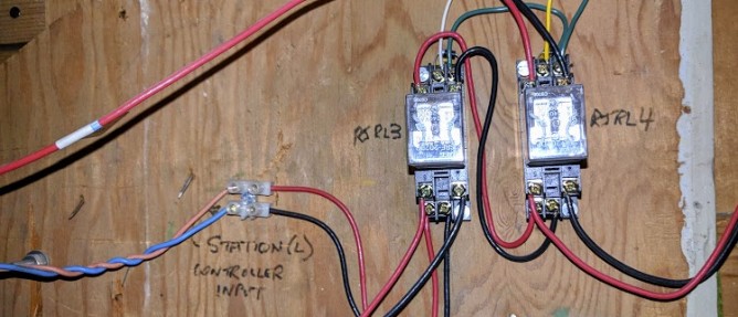
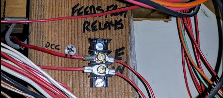
My solution is to bring power to the unused Local Station West Terminal. That powers the currently unpowered garage tracks. It also powers lines 1-4E and 1-4F which are used by RJRL3 when T311 and T504 are normal (e.g. not thrown towards mainline). When T311 and/or T504 are thrown, power is routed by RJRL3 and RJRL4 to B321 or the Branchline, respectively, by feeding them to connection 1-4D which goes to the E/W 2-position terminal. I’d instead disconnect W from the current E/W terminal and bridge to the same red lead feeding the Local Station West Terminal.
In the end, I will use an actual power terminal and only need to disconnect one single wire as such.
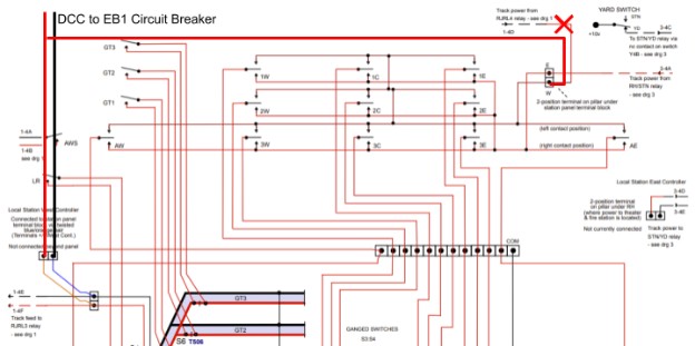
As the image above is likely a bit fuzzy, please look at the original drawing #4 on the Station Schematics.
RJRL3 and RJRL4 are located somewhere under Rodger’s Junction.
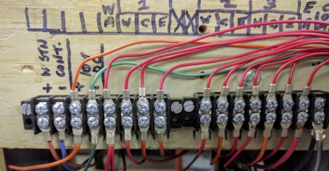
The “Local Station West Terminal” can be found there too and it connects to...
...the “+ W STN / - CONT” behind the Stockton Passenger Panel.
The “E/W” feed terminal, behind the concrete pillar by the station.
This scheme leaves the current “East” position of each station block routed the same way. Currently we have:
“West = Nothing / Middle = Nothing / East = DCC from Stockton Yard”.
In the new scheme, we’ll have:
“West = Isolated DCC Power District / Middle = Nothing / East = DCC from Stockton Yard”.
We’ll be able to use the new or old scheme by using the block power selectors on the panel.
We’ll likely want to run with the “East” approach (Stockton Yard) side powered from the East side (e.g. via the Stockton Yard), and then power all the rest using the “West” approach (which will be the new DCC power district).
This will likely resolve one issue we have right now, namely that the automation train stopped at the station is affected by switching and shorts that occur in the Stockton Yard.
I’d like to point out that all this layout was designed with the “common ground” pattern, thus all the panel blocks only cut one side of the power (the red side here). Some parts of the layout are fully isolated, and some still have remnants of the old “common ground” pattern. It’s a bit of a mixed bag, yet the black common side of all yards and panels is common for all the power boosters.