The Randall Museum in San Francisco hosts a large HO-scale model railroad. Created by the Golden Gate Model Railroad Club starting in 1961, the layout was donated to the Museum in 2015. Since then I have started automatizing trains running on the layout. I am also the model railroad maintainer. This blog describes various updates on the Randall Museum Model Railroad and I maintain a separate tech blog for all my electronics & software not directly related to Randall.
2021-01-09 - Work Update on T150, Panels, and Lights
Category RandallToday’s visit on the layout was mostly fixing some little overdue things.
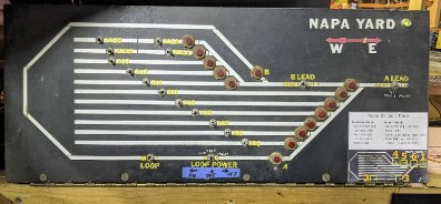
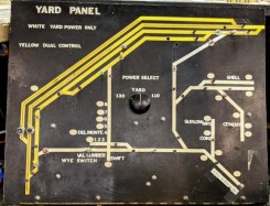
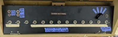
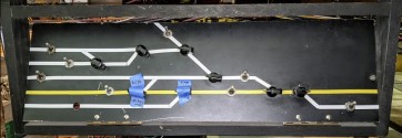
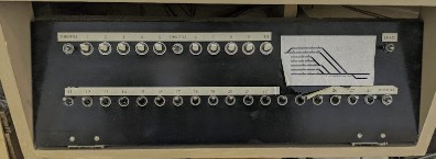
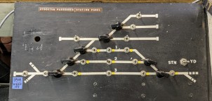
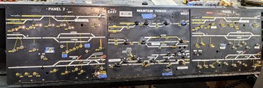
To get started, I dusted all the yard panels. This has to be done very carefully to not damage the delicate inscriptions -- some of these decals are quite old and unglue very easily.
|
|
|
|
|
|
|
|
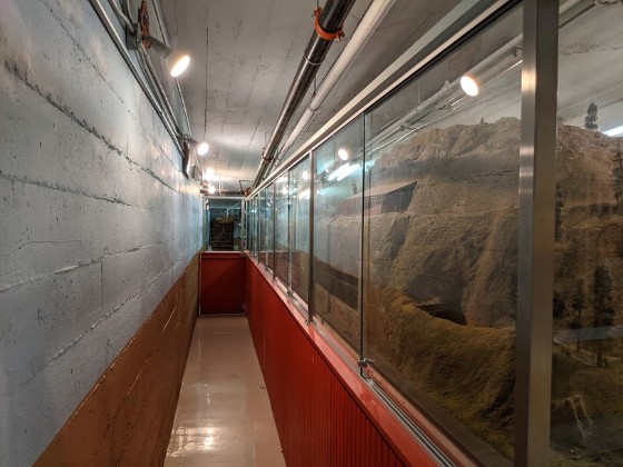
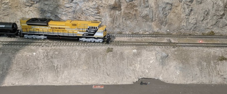
I rearranged the lights on the side of the mountain to remove dark spots; it is now somewhat properly illuminated:
I added the status light to the T150 turnout (from mainline towards Sultan). DCC control of the turnout had been added last year, and status lights had been added to turnouts T151 and T160 a few months ago.
Now all the three controllable turnouts to Napa / Sultan have status lights. As with the other ones, there's only one red light when the turnout is divergent, there is no green/red. These are not trying to be prototypical ABS or CTC, they are merely warning lights in case operators leave mainline turnouts thrown.
Red status light when T150 is thrown.
The LED is a 3mm red LED. It measures a Vf of 1.89 V.
A 2.2 kΩ resistor is soldered in line, then two extension wires are soldered.
A 3/32” or 1/8” hole is drilled from the top and the whole assembly is dropped from the top.
A 5/32” is used from the bottom to enlarge a bit the plywood passageway for the cables.
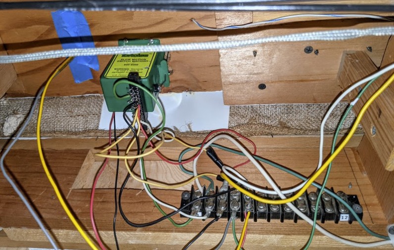
Under the layout, the two wires are directly connected to the frog power (green at 4th position) and an opposite rail (black or red in 3rd or 5th positions).
Since we are connecting directly to the DCC, polarity does not matter.
On the terminal from left to right: 1 Green + 2 White = turnout control; 3 Black + 5 Red = Rails A/B; 4 Green = frog.
The status LED has wires gray+yellow, connected to the green frog + red rail.
Important consideration: the LED will be in reverse voltage for half the DCC signal duration. Red LEDs can supposedly stand a large reverse voltage whereas green / orange / blue ones cannot [citation needed]. A typical design workaround is to add another diode in reverse to the LED to avoid that reverse voltage.