The Randall Museum in San Francisco hosts a large HO-scale model railroad. Created by the Golden Gate Model Railroad Club starting in 1961, the layout was donated to the Museum in 2015. Since then I have started automatizing trains running on the layout. I am also the model railroad maintainer. This blog describes various updates on the Randall Museum Model Railroad and I maintain a separate tech blog for all my electronics & software not directly related to Randall.
2022-02-15 - Randall Repairs: Turnout T161 (4th fix)
Category RandallAffected |
Turnout T161 (end of siding between Bridgeport & Sultan). |
Description |
Intermittent loss of power on frog. |
Summary Fix |
Add bond wires to power turnout stock rails from B161. |
Description of Issue
For a while we’ve had issues with the turnout T161. Trains would stop dead on the turnout. Other times they worked fine. Some trains could go through just fine yet we would have issues with steam engines.
Back in 2018, I identified the frog power showed a clear resistance, and posited it was due to faulty contacts in the Fulgurex. After changing the switch machine in 2018, the problem went away. Then since last year we’ve had intermittent issues again with this.
Two weeks ago, I did two things. First I hardwired the turnout for the straight route. Now the frog is always powered directly from the proper stock rail. The switch machine contacts powering the frog are entirely bypassed. The other thing I did is take an overhead picture of a similar turnout and color the rails to clearly understand the power routing of the turnout.
The “fix” from two weeks ago did not last long. At the next operating session, trains stopped on the turnout again. However this is good as it helped eliminate the Fulgurex as the culprit. It is not an issue of frog power routing. We also know that the turnout sometimes works fine, so I suspect a bad solder join or something similar on the way the turnout gets its power, something that varies with time & temperature as the track can expand or shrink -- a problem we have in a few other locations on the layout.
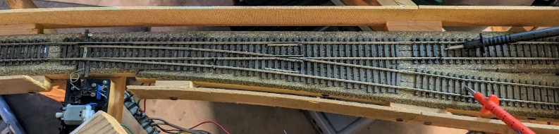
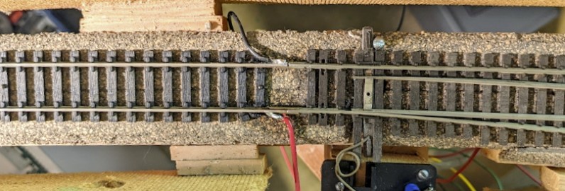
Here’s a picture of T161:
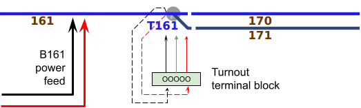
And here’s the same picture, annotated to understand power routing:
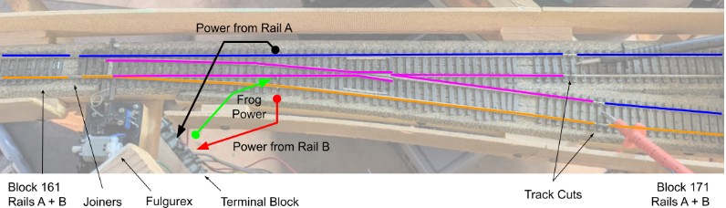
Now I understand how this all works:
- The frog (all the purple lines) is powered by the green wire from the terminal block.
- The terminal block takes its source power from the stock rail A and B on the turnout. There are 3 solder points visible in the middle of the turnout, one on each rail and one on the frog.
- The turnout is cut from the track on the B171 (right) side. There are gaps in the track and the turnout is fully isolated from the B171 block.
- The turnout is connected to the track on the B161 (left) side. There are metal joiners between the B161 rails A and B and the corresponding turnout stock rails.
An issue I can see is with these joiners on the left side. They are loose and make a poor connection. When tested closely with all the track power off and testing continuity with the multimeter, it was clear both sides made a poor connection and I could establish the connection by just pushing the rail a bit.
Description of Fix
One may be tempted to entirely solder both sides of the joiners to make a strong bond between the rail and the turnouts. However, that is not desirable. We have had issues with track expansion and we need the track to be able to move a bit, which these joiners allow it to do. My proposed solution is to:
- Solder one side of the joiner to the track on B161, and let the other side “loose” on the turnout stock rail.
- Solder two power feed wires (black and red) directly to the rail on B161 that will bring power to the terminal block.
I have done the first part and it looks something like this:
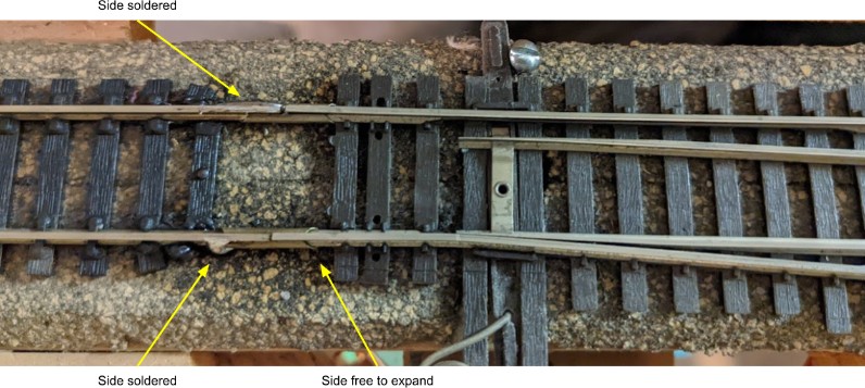
By the way, the image above gives us a good view of the screw that Allen used to “spike” the throw bar (later, once we have the turnout electrically solved and guaranteed to work, I plan to remove the screw and rewire the turnout to be able to throw it as needed).
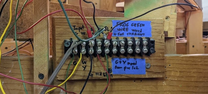
The second part is to use these 2 solder points and solder a wire that will be connected to the terminal block:
This way the electrical connection is solid -- that is the stock rails are powered by the rails from B161 via “bond” wires. Yet at the same time the joiner allow to compensate for track movement or expansion as it is not fixed on the side of the turnout. Here’s the result:
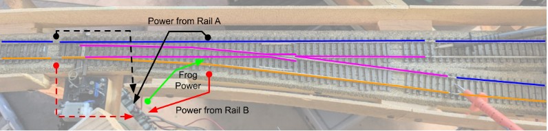
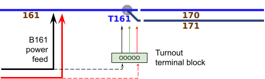
As a schematic (dotted lines represent the new bond wires):
The picture above shows the two new wires that take power from the B161 rails (just before the joiners). They connect directly on the terminal to the wires going to the corresponding stock rails:
Since I was in there, I also tried to reconnect the switch machine to power the frog. It worked fine till I tried to throw the turnout back and forth. Doing so resulted in an immediate short, bridging both stock rails. I need to investigate this more before I can reactivate the switch. As it is right now, it works at least for the straight route with the frog hardwired for this position.
Alternate Possible Fix
Thinking about it after the fact, I realized there would have been another way to solve the power issue. The switch machine powers the frog by taking power from the two outer stock rails, and powering the frog via a contact. The core issue is that the rail joiners were not making a good contact with the turnout stock rails. Thus I solved that by grabbing power from the block B161 via bond wires. But instead, what I could have done is fine where the block B161 gets its power from and run power feed wires directly from there to the turnout’s terminal block.
As a schematic (dotted lines represent the new bond wires):
The only uncertainty here is that, first, I don’t have a clue where B161 gets its power from. Of course that’s a simple matter of crawling under the layout till I find the feed wires. Because this used to be a common-rail DC layout, most often that not, the way this is wired under the layout is that the “common” rail is (conceptually) one continuous wire with taps for each blocks, whereas the “hot” side comes from the block panel. Except often it’s not even that, as one additional complexity one the mainline is the old obsolete track detection system (see "A Mountain of Wires") which means the the common-rail side goes into one bundle somewhere before merging to the common terminals, whereas the “hot” rail side goes to the panel. Still, it should theoretically be possible to find that block feed and tap into it to feed the turnout directly at the terminal block instead of taking power from the actual rails.