Model Train-related Notes Blog -- these are personal notes and musings on the subject of model train control, automation, electronics, or whatever I find interesting. I also have more posts in a blog dedicated to the maintenance of the Randall Museum Model Railroad.
2025-03-26 - Distant Signal: Matrix Display for Turnout T330
Category Arduino
Here’s a new project, Distant Signal: https://github.com/model-railroad/distant-signal
The goal of this project is to display the state of a remote model-railroad turnout on a LED Matrix Display. That’s obviously the “phase 2” of the single-LED ESP32 display I toyed with last week.
The hardware for this project is an AdaFruit MatrixPortal ESP32-S3 driving an AdaFruit 64x32 RGB LED Matrix - or more exactly some clone/equivalent of such.
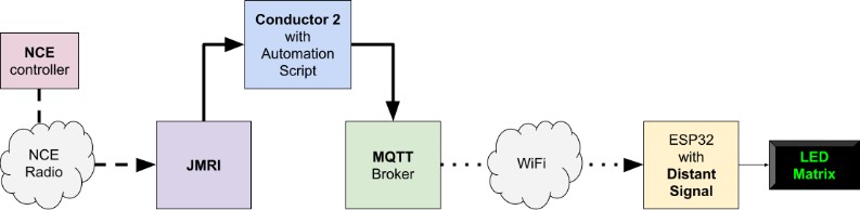
Overall, the project works exactly the same as the single-LED version did:
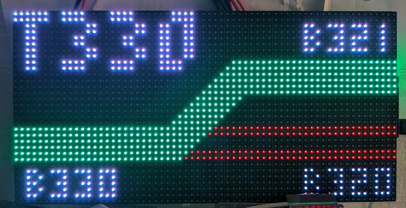
Here’s the first iteration of the display:
This version uses a basic text-based configuration script to define the content of the screen:
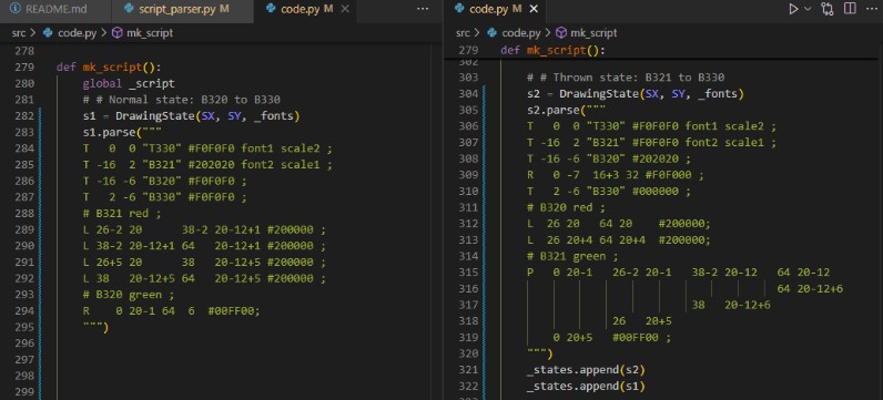
That’s the configuration script that the Conductor automation program would send to the display to initialize it. The configuration script defines several “states”, for example “T330 normal” vs “T330 reverse”. Each state is describes the entire content of a screen using a set of graphic primitives -- line, rect, text, and polygon.
Then MQTT would be used to select which state to display -- in this case turnout states, as the automation dictates which state should be displayed based on turnout sensor feedback. From the ESP32 point of view, the behavior is totally agnostic -- all it does is display a full screen of “something”.
2025-03-20 - Indicator for Turnout T330
Category Arduino
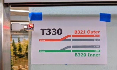
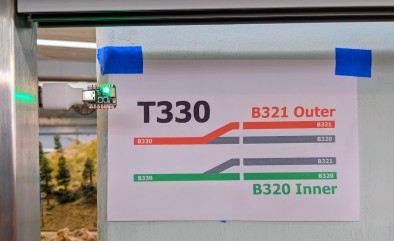
Here’s a new a experiment: we now have a new visual indicator of the position of the Sonora turnout T330, designed to be visible by the Saturday operators when standing at the Stockton Yard:
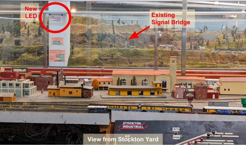
Sonora has the two mainline tracks that merge together at turnout T330, and there’s a signal bridge with signals that clearly indicate the position of the turnout. The problem is that the signal bridge is not visible from across the layout, where the operators are typically standing.
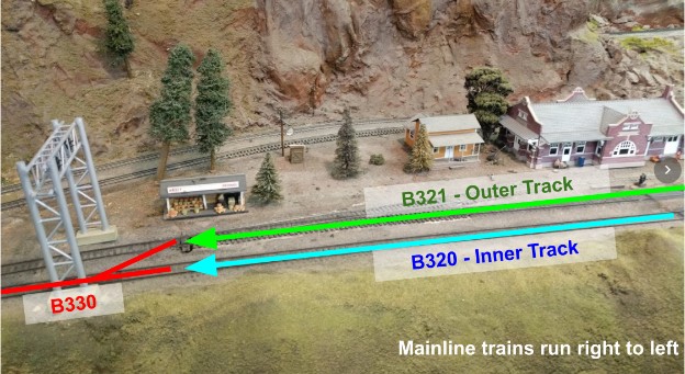
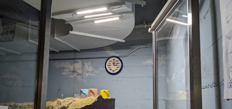
Thus this new experimental signal is located on the pillar -- it’s facing the operators, and it’s high behind the window, hopefully high enough to be visible even when the public is present in front of the layout.
I kept the new signal as simple as possible: green indicates the turnout is aligned straight for the “inner” track (block B320) and red indicates it is thrown for the “outer track” (block B321). Behind the signal, I placed a short explanation to hopefully make it clear what the color represents:
Click here to continue reading...
Back in December I was fighting with the spurious block activation of block B360. This would break the automation, and I would have no real report about it. Of course I already have a custom web dashboard that shows me the status of the automation and after-the-fact analytics -- what kind of automation would that be without such dashboards? Still I figured having a “realtime” notification on failure would be better than periodically checking my custom dashboard.
I could add some email-sending capabilities to Conductor 2, but that’s something I’d rather not do as it’s a bit of its own rabbit hole. The Debian Linux computer running Conductor 2 has no email capabilities, and I intend to keep it that way -- I treat it as what it is, namely an unsecured box in a public museum with fairly loose access, thus it’s basically a DMZ.
Instead what I want is for the emails to be generated by some server that I control. All I need is to get the data to that server. I could piggyback the errors on the JSON used by the RTAC status server. That would almost be too logical. Or I could publish it on the MQTT broker and then proxy it over to the email server. Well, if I’m going that route, what about RSyslog?
So that’s what I did, and I get this kind of beautiful emails:
From: pi@alfray.com To: self@alfray.com Subject: New Automation Error Date: Wed, 08 Jan 2025 11:00:11 -0800
Jan 8 11:00:01 consist fireman: CONSIST ERROR: 10:57:38.342 R Sequence Branchline #3 Shuttle (0204) : ERROR Sequence Branchline #3 Shuttle (0204) current block <BLYouBet [NS760]> still occupied after 120.5 seconds. 10:59:38.892 R Sequence Branchline #4 Recovery (0204) : ERROR Sequence Branchline #4 Recovery (0204) current block <BLYouBet [NS760]> still occupied after 120.0 seconds. |
Here’s how I implemented this:
Click here to continue reading...
2024-12-25 - Conductor 2: Activated Block Handling
Category Rtac
These two commits address the recent issue of spurious block activation breaking the automation.
Recently a new sensor-related issue arose with block B360. Last time, it was because some track was occupied somewhere else on the layout. This time, the issue is different: the automated passenger train is going to Summit (the top of the mountain), where it stops and returns back down. It goes through these blocks:
B370 (Summit) → B360 → B340 → B330 → B321 → B311 (Station)
The new problem with block B360: after the train has left block B360 and entered block B340, block B360 should register as “empty”. After all, the train isn’t on the block anymore. But from time to time -- very rarely -- the block will keep staying on, sometimes as long as a minute and half! Now two adjacent blocks can be active at the same time -- that happens when a train crosses a block boundary. But once the train reaches block B330, it is an error for block B360 to still be active.
When that happens, the automation enters the error mode, stops the train, and tries to do a recovery. Interestingly as soon as the train stops, that “frees” block B360 too. Thus the recovery mechanism notices that only block B330 is active, deduces the train must be there, and brings it back home. From a viewer point of view, that all happens almost instantly so it’s hard to notice visually that something went wrong. But from a software perspective, it was all wrong for sure.
Click here to continue reading...
2024-12-16 - Conductor 2: New MQTT Support
Category Rtac
There’s been a few changes in Conductor 2 in the recent weeks.
The first major change has been to add MQTT support. The custom script language now exposes an “mqtt” object. Once configured, one can publish MQTT topics/messages. This is used to control the Ambiance LED string display. Here’s an example of usage in the latest script:
mqtt.configure("~/bin/JMRI/rtac_mqtt_conf.json")
mqtt.publish("ambiance/script/init", "Brightness 0.5 ; Fill #000000 1 ; SlowFill 0.1 #FF1000 40 #FF4000 10") mqtt.publish("ambiance/script/event", "Slide -0.05 100")
var _ambiance_counter = 0 fun Ambiance_Trigger() { mqtt.publish("ambiance/event/trigger", _ambiance_counter.toString()) _ambiance_counter++ }
fun Ambiance_Off() { mqtt.publish("ambiance/script/init", "Brightness 0.5 ; SlowFill 0.25 #000000 1") } |
Click here to continue reading...
2024-11-25 - Red Side Door USB Light
Category Electronics
This is what I used for the red door: https://amzn.to/43dp9e9 “USB Lights Bars 12 Inch, 3 bars chained”.
I’m powering this with a custom-made USB A-to-C adapter, which is turned off and on by a contact switch on the door. That works well, but it’s been bugging me because the light is stuck in the white-ish 9000K mode instead of the better looking 3500K 6500K mode. So I took one apart to see how it is built inside.
It contains a USB C with a 6-pin connector. That’s a “power-only” connector: GND / VBus / CC1 / CC2 / VBus / GND.
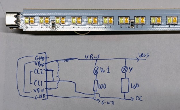
So essentially they “abuse” the CC1/CC2 lines as ground for the yellow-ish LEDs.
Click here to continue reading...
2024-11-21 - DC-DC Boost Step-Up Converter XH-M411
Category Electronics
I got these for Randall and they are working very nicely: https://amzn.to/4evzCYk “DC-DC Boost Converter, XH-M411 DC to DC 3-35V to 5-45V (2 pack)”. The cost was $6.50 per converter.
There’s no usage manual (or I lost it?), so let’s copy stuff here:
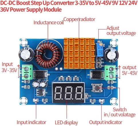
What the button does is switch the display from displaying input to displaying output voltage. The blue LED turns on on the input/output side depending on what is displayed.
Output voltage is adjusted using the tiny blue potentiometer next to the radiator.
Click here to continue reading...
In the old Conductor 1, anytime the train sequence did not work as expected, the engine simply stopped everything, and we had to manually replace the trains as expected and restart everything.
Thus, when I redesigned the new Conductor 2, I added some “recovery” functionality -- the idea is that if the train sequence does not happen as expected, the automation engine should do something to try to recover the trains.
Unfortunately, the idea of “recovery” is basically to more or less predict the unpredictable and decide what the automation program should do in that case. Which means there are always cases that one never thought about because that “could never happen” and thus such cases are not handled. Today is one such case.
Orion and I have been slowly working on fixing the Branchline T324 turnout. That involves crawling through one of the mountain access holes, and then we need to reach the Branchline over the Mainline track. To make it more fun, that’s one of the tracks used by the Passenger train automation.
Twice I’ve seen the Passenger train go into error mode while we were trying to work on the Branchline T324 turnout. What was even more puzzling is that the Passenger was at Summit and then the Freight train just… started! Suddenly, on the same track, I had the Passenger train go into recovery and thus reversing towards the station whilst at the same time I had the Freight train leaving the station… Each going towards each other in the opposite direction. Not exactly a good scenario.
Hilarity ensues.
The first part of the puzzle was easy to find: when we crawl into the mountain access hole, we somehow activate the block B340. It’s not exactly clear why and how that happens, yet that sure is the result.
Here’s an excerpt from conductor-log-2024-10-12-08-40-03.txt:
Click here to continue reading...
2024-10-12 - Conductor 2: Sensor Issues on B330 and B360
Category Rtac
This happened once, when Allen and Jim ended their Saturday session:
- At 1:40pm, they turned the "Saturday mode" switch off, turned the Mainline Automation toggle on. Consequently, the Freight train correctly moved back to its normal position.
So far that seems normal. However...
- At 1:42pm and 1:43pm, the computer registered multiple on/off instances of block detection on Block B330 -- there were about a dozen on/off activations for 2 seconds -- but also B360 registers as on -- see below.
- Cameras show they were not running anything at that time, and that block B330 is clearly empty. I cannot see B360 however nothing on the video indicates there should be anything on it (no trains going in or out in the following minutes).
- Camera shows Allen moving trains to Richmond via B160/B150 a minute later. I don’t think it’s related.
Here’s an excerpt from conductor-log-2024-10-12-08-40-03.txt:
⇒ This starts just after the Freight train has reached its default parking location at the Station:
13:42:34.779 R Idle Mainline #0 ML Ready : ACTIVE
13:42:35.972 S S/NS773 B330 : ON
13:42:36.937 S S/NS773 B330 : OFF
13:42:37.833 S S/NS773 B330 : ON
13:42:38.962 S S/NS773 B330 : OFF
13:42:39.659 S S/NS773 B330 : ON
13:42:40.639 S S/NS773 B330 : OFF
13:42:41.520 S S/NS773 B330 : ON
13:42:42.416 S S/NS773 B330 : OFF
13:42:43.348 S S/NS773 B330 : ON
Click here to continue reading...
The Software Defined Blocks project uses an ESP32 with sensors to emulate block activations for a train model railroad.
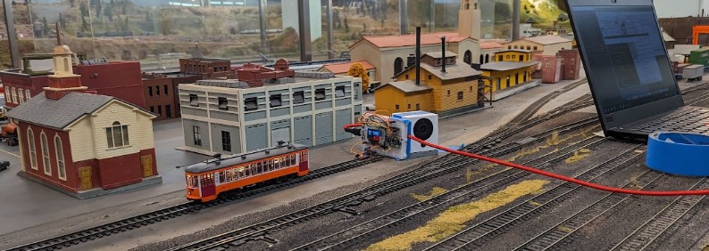
The first prototype automation test has been overwhelmingly problematic:
- At first, I could not get the ToF sensor to reliably detect the engine. It would seem to work, then most of the time it would not detect a decreasing distance as the trolley was approaching till it was right next to the sensor.
- At the same time, my mere presence a couple feet on the side would influence the result. That’s not good.
- The response time in JMRI seems extremely slow.
Let’s detail that last one.
Click here to continue reading...