Model Train-related Notes Blog -- these are personal notes and musings on the subject of model train control, automation, electronics, or whatever I find interesting. I also have more posts in a blog dedicated to the maintenance of the Randall Museum Model Railroad.
2022-02-23 - How Not to Use Split Core & HAL Sensors for DCC Block Detection
Category TrainFor now I’ve been doing block detection on the Randall layout using NCE BD20 current detectors. They work well. There are others DCC-compatible detectors but they all use through-hole core transformers, which means they cannot be used with existing wiring without desoldering or disconnecting something.
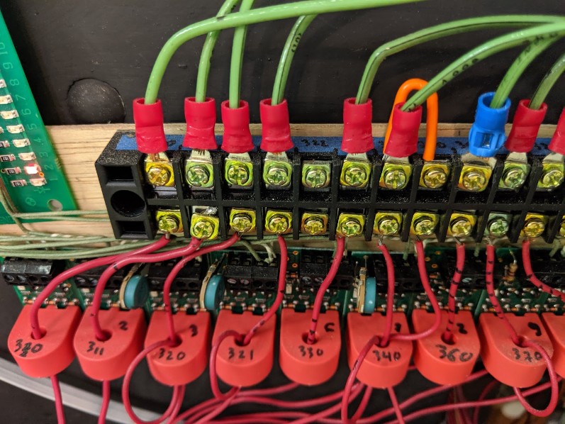
There are other contenders to the BD20, such as the cpOD and the CKT-BD1. I plan to switch to these once I exhaust my current supply of BD20. But the bottom line is that they all use these “through-hole CT”, and sometimes I wished I had the convenience of a split core transformer that I could quickly snap around a track feeder wire.
Thus a while ago I two sensors, with the purpose of connecting them to an ESP32 and monitor train track current:
- https://amzn.to/3q7qG4z Hall-sensing ACS712-5A current module.
- https://amzn.to/3AJM5FP Split core SCT013-005 5A 1V current transformer.
Spoiler alert: I discussed that topic on the MRH forum and the Arduini forum and I was clearly told that would not work, and to make a long story short, I never managed to make them work for this application.
Upfront I want to indicate why that was anyway not a surprise and I was likely to fail:
- My end goal would have been to connect the sensors pretty much directly to an Arduino or ESP32 with no other circuitry, and then deal with the sensor in software.
- By contrast the BD20, even though it’s the one with the simplest board, still clearly has 4 diodes (likely a bridge rectifier), 3 transistors, and a few other discrete SMD components. The coOD and the CKT-BD1 have even more circuitry, including a small microcontroller likely to perform some noise filtering.
- The split core transformer I got as well as the ACS712 are typically used in home automation systems to monitor live voltage current anywhere from 1A to 100A, and at either 50 or 60 Hz. By contrast, current on a DCC track feeder may be maybe 2~4A max on a heavy load, and our DCC signal runs at89 kHz. But the point of the block detectors above is to be extremely sensitive -- they will detect an engine not running and sitting idle on the track when properly configured!
Anyway, I’ve done the test and I failed. I’d venture one could probably use these sensors with some additional circuitry, but I have not tried that yet -- my goal was not to replicate the behavior of the dedicated sensors cited above.
ACS712 Module
The https://amzn.to/3q7qG4z ACS712-5A is already mounted on a 3-pin “arduino compatible” board. This one is rated at 5 amps, which is the minimum available.
Here’s the ACS712 data sheet from allegro:
- Chip: ACS712ELC-05B
- Supply power: 5V (min 4.5V, typ max 5.5V)
- Measuring range: 5A
- Analog output: 185 mv/A
- When there is no the detection current through, the output voltage is VCC / 2
Application note #4 show output should be placed on a resistor divider for a typical 3.3V ADC. Shows a 1 nF cap on filter pin 6. There's a diode and a "user cap" too.
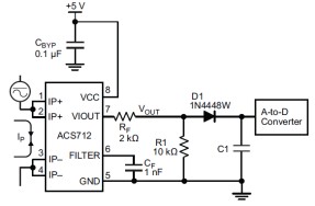
Do I need D1 & C1 on this application?
What is the little board schematics?
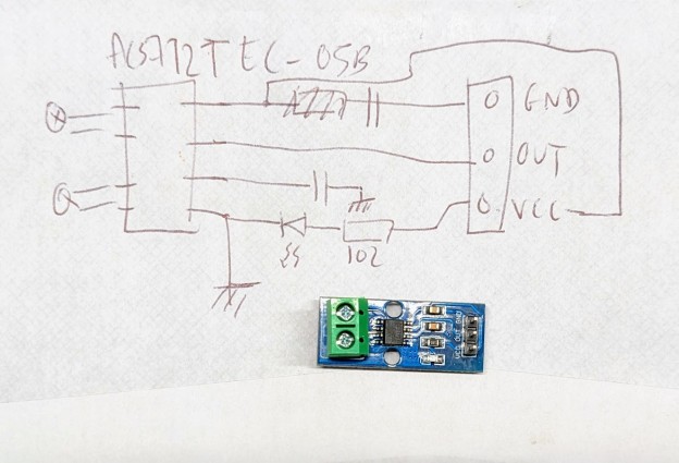
I couldn’t measure the values of the caps on the board.
The design matches the application note:
- There’s a cap between VCC and GND. Let’s assume it’s 0.1 uF.
- FILTER pin connects to GND via a cap. Unfortunately that’s the one I’d like to know the value of and I can’t seem to measure it. It’s a slightly different shape than the one on VCC and we can infer it’s likely not the same value, whatever value that is.
- VIOUT pin connects directly to OUT with no other circuitry. It’s up to me to build a voltage divider.
- LED is driven directly off VCC via a 1000Ω resistor. I couldn’t measure the Vf but looking at samples from Mouser a typical green red SMD LED would be either around 2 V or 3.3 V.
- 5V-2V=3V / 1000Ω = 3mA.
- 5V-3.3V=1.7V / 1000Ω = 1.7mA.
⇒ When trying the schematics above on a single wire of DCC bus with a single engine running, and looking at the output using a small digital scope, I get basically nothing but noise. Signal is at ~2.04 V and doesn’t move from there. By contrast, a single through-wire with a BD20 triggers instantly in the same conditions.
I’m not going to dwell too much on that sensor since I’d rather have something with the convenience of a split core that I quickly snap around an existing wire, without having to cut it.
Split Core Transformer
The https://amzn.to/3AJM5FP split core is a 5A/1V model with a sampling resistor.
There are two versions of these split cores:
- Without a resistor: it’s a coil, and one measures amps out of it.
- WIth a resistor: a resistor with the internal coil, and one measures voltage across that resistor.
I have the latter one.
What’s inside:
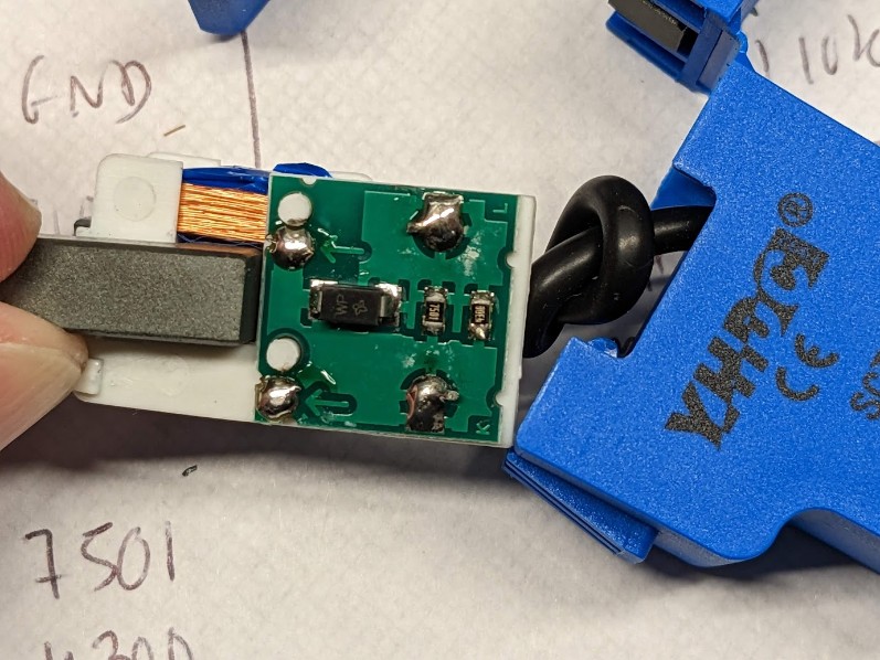
- An SMD marked “WP”. That marking could denote a diode or a “transient voltage suppressor”. The latter seems more likely. Here’s such a Vishay component.
- 2 resistors in parallel, marked 4300 and 7501: 430 Ω // 7.5 kΩ. Eq = 406 Ω.
Let’s compare this with the specs of 5A ⇒ 1V.
- U=RI ⇒ 1V = 406Ω * I ⇒ I = 1/406 = 2.46 mA.
- 5A/2.46mA gives a ratio of 1:2030 for the primary/secondary windings.
Datasheet found online, https://datasheetspdf.com/pdf/1328320/YHDC/SCT-013-050/1:
Some notes:
- Output is a 3.5 mm jack with 2 outer rings used (middle one “vacant”).
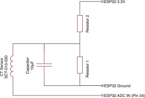
- All the ESP/Arduino schematics I find using the SCT013 in voltage mode power it via a 2-resistor voltage divider with a 10 uF cap (example). None explain why.
- Another one points out they use a 5V input, so the voltage divider is to ensure they feed the xfmer with only 2.5V, below the 3.3V threshold of the ESP32. I think the other ones copy-paste that principle without even asking whether it’s sound. But a better explanation: output will be zero and +/- so it’s easier to deal with if it’s centered on half the analog Vin reference voltage -- which is exactly how an ACS712 operates.
- It would make more sense to power from xfmer from the 3.3V output of the ESP32, which is what the first example does.
We’ll use this connection:
⇒ When trying the schematics above on a single wire of DCC bus with one engine running, I get basically nothing but noise. There seems to be a voltage when measured solely on the output of the sensor using the digital scope only. The scope registers it in the 24 mVmrs range. I can’t measure it with a voltmeter. It’s very inconclusive.
Even when trying to loop one DCC wire 3 times around the coil, I got absolutely nothing. By contrast, a single through-wire with a BD20 triggers instantly in the same conditions.
Let’s play with that schematic anyway.
R1+R2 is a voltage divider, listed as “either 10kΩ or 100kΩ”, connected to either the 5V or the 3.3V Vout (the schema above clearly calls for the latter).
Impedance of C + R1 in parallel: 1/Z = 1/R1 + jwC where w = 2.pi.f
https://keisan.casio.com/exec/system/1258032649 calculator:
- C = 10 uF
- f = 8 kHz, R1 = 10 kΩ ⇒ |Z| = 1.9894367492791 Ω.
- f = 8 kHz, R1 = 100 kΩ ⇒ |Z| = 1.989436788255 Ω.
- f = 50 Hz, R1 = 10 kΩ ⇒ |Z| = 318 Ω
- f = 50 Hz, R1 = 100 kΩ ⇒ |Z| = 318 Ω
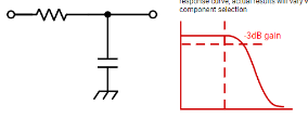
Another way to see it is that R2 + C forms a low-pass filter if we ignore R1. Let’s compute the cut off frequency at -3 dB using fc = 1 / 2.pi.R.C:
- R2 = 10 kΩ ⇒ fc = 1.59 Hz
- R2 = 10 kΩ ⇒ fc = 0.1592 Hz
So this will be filtering our 8 kHz massively.
Let’s do the reverse computation:
- fc = 8 kHz, R2 = 10 kΩ ⇒ C = 1.98 nF ⇒ C//R1 |Z| = ~7.1 kΩ at 8 kHz
- fc = 8 kHz, R2 = 100 kΩ ⇒ C = 198 pF ⇒ C//R1 |Z| = ~71 kΩ at 8 kHz
- fc = 10 kHz, R2 = 10 kΩ ⇒ C = 1.59 nF ⇒ C//R1 |Z| = ~7.8 kΩ at 8 kHz
- fc = 10 kHz, R2 = 100 kΩ ⇒ C = 159 pF ⇒ C//R1 |Z| = ~78 kΩ at 8 kHz
Side note: -3 dB is ~70% of the signal, which is why the ~7k/70kΩ impedance above is to be expected as being ~70% of R2.
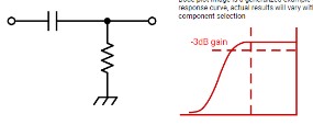
Low-pass vs high-pass:
The bottom line is that all these example schematics are designed to measure 50~60 Hz AC current so I’d have to expect to adjust the cap value for my 8 kHz need. From a discussion on MRH/Arduini, I should expect the magnetic core/coil to be improperly matched for my needs, and as seen above obviously the capacitor would need to be adjusted.
In my case, I want to measure a DCC signal, and a typical usage is going to be 1~2 Amp max, so around 200~400 mV is the theoretical output delta, and clearly I’m not getting that.
Depending on how one sees the DCC signal, it’s either a +/- signal or a +/0 square signal. Depends on the reference level obviously.
The original goal was “without added circuitry”. I tend to think maybe a bridge rectifier on the output would be useful.
More importantly, I want to use this similarly to how I’d use a BD20, which means as current detector “all or nothing”. Which means what I really want is to sample the noise when there’s no current, and then detect as soon as there’s something that is not zero, and it assumes I can differentiate a signal from just noise.
Bottom line, we confirmed neither sensors are appropriate for the task as-is. That’s exactly what comments in MRH & Arduini indicated, and it was worth verifying.