Model Train-related Notes Blog -- these are personal notes and musings on the subject of model train control, automation, electronics, or whatever I find interesting. I also have more posts in a blog dedicated to the maintenance of the Randall Museum Model Railroad.
2022-03-15 - Dead Spot Detection Car for DCC
Category TrainHere’s my latest DIY experiment: a homemade “dead spot detection car”.
Here’s a schematic and a rough explanation of how it works:
This is designed to work exclusively on DCC track.
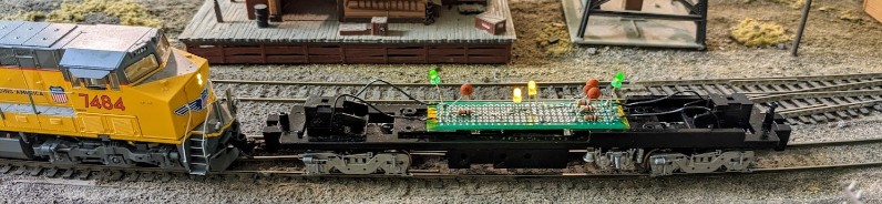
The goal is to help operators detect dead spots on the track, either by rolling the car manually or by pushing it with an engine as seen above. They need to move it till the front green LED turns off. That will allow us to determine where the break in the track continuity is located. Then using the yellow LEDs, we can determine if the break is in only one rail or both rails.
This isn’t just about breakage in the rails, either. The original motivation was to help me find issues with unpowered frogs on the layout’s turnouts. In this case by moving the car manually over a turnout, we should be able to see a green LED go off when the frog or the closure rails are not powered correctly.
When building this, LEDs polarity does matter as shown in the following electrical schematic:
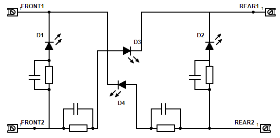
Each diode has a 10 kΩ current-limiting resistor and a 100 nF capacitor for smoothing (ceramic with 104 marking).
The polarity of the LEDs relative to each other does matter -- both green LEDs must point in the same direction relative to the track, and the yellow LEDs must share a common cathode with their counterpart green LED.
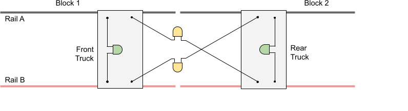
The two green LEDs measure the voltage across opposite sides of the front or rear truck respectively. When the track is powered in DCC, rails A and B always have opposite polarities and thus the LED illuminates. Since DCC is a form of “alternating” voltage, the LED will illuminate regardless of the direction of the car (which is why this can work in DCC yet it won’t work in DC).
In summary:
- Correct: The green LED illuminates if both rails have the “correct” DCC signal for that specific truck (front or rear).
- Incorrect: The green LED will be off if both rails have no voltage or have the same voltage.
When moving the car across a block boundary with one block turned off, at some point one of the green LEDs will turn off while the other one stays on. That allows us to trivially find the block or the dead spot boundary.
The two yellow LEDs measure the voltage across diagonals between the front and rear truck. In normal conditions they should also both illuminate when the front and rear truck are powered correctly.
Randall uses an old DC common rail design, which means every single rail from one side is connected together. When we reach a block boundary and the block is turned off, actually only the “positive” rail is cut off. In that case, one of the yellow LEDs will stay lit whereas the other one will turn off. If both yellow LEDs turn off, that means the common rail is also cut off, which is not expected on an old-style layout such as the Randall one.
In summary:
- Correct: Two yellow LEDs on.
- Incorrect: One yellow LED off and one yellow LED on means only one rail (on the side that is off) has no power.
- Incorrect: Both yellow LEDs off means no power on both rails for one of the trucks.
Example in usage:

In the picture above, the car is sitting on the transition between blocks B21 and B30. They are both powered, is which is why both green LEDs are lit, as well as both yellow LEDs.
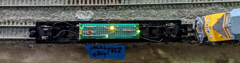
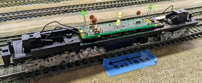
In this new picture above, block B21 has been toggled off. The front truck is no longer powered and thus the front green LED is turned off. However toggling B21 off only cuts the outer rail (bottom one of this picture), which is why the bottom yellow LED is now off. Since the top rail is the common rail, it is still connected and thus the top yellow LED is still lit. That’s “working as expected” for this common rail design.
If the top yellow LED were off too, we would know there’s a connectivity issue in the common rail side.
Update 2022-05-12: A one-page user manual has been posted here (PDF to download):
Randall Dead-Spot Detection Car [2022-05-12].pdf