Model Train-related Notes Blog -- these are personal notes and musings on the subject of model train control, automation, electronics, or whatever I find interesting. I also have more posts in a blog dedicated to the maintenance of the Randall Museum Model Railroad.
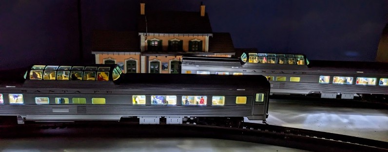
2023-01-08 - Lighting a Walthers Mainline Dome Coach Car
Category DCC
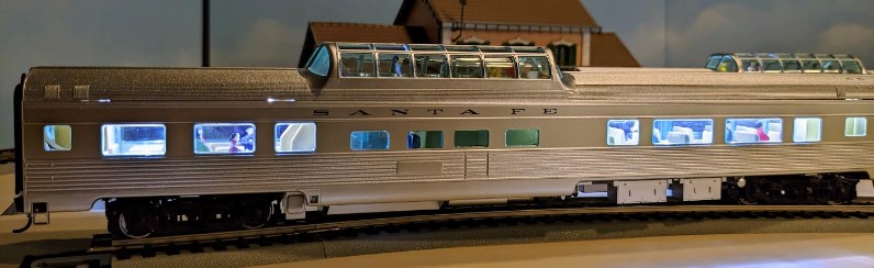
Allen has a number of these Walthers Mainline Santa Fe cars, the 85' Budd Large-Window Coach Santa Fe (910-30002) and the 85’ Budd Dome Coach Santa Fe (910-30402):
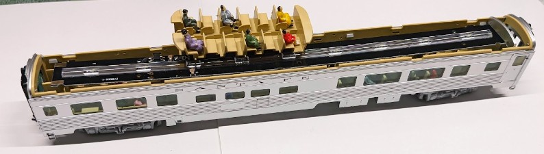
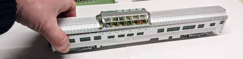
Walthers Mainline 910-30402 85’ Budd Dome Coach Santa Fe.
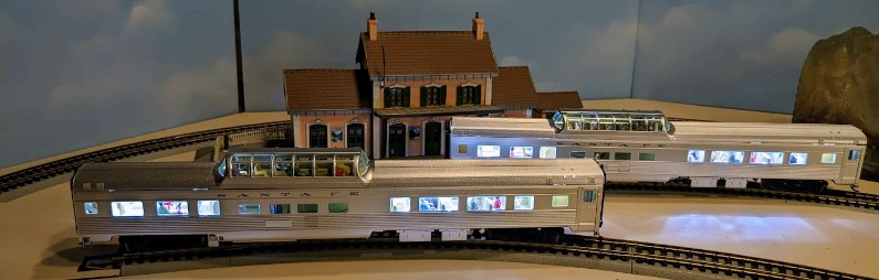
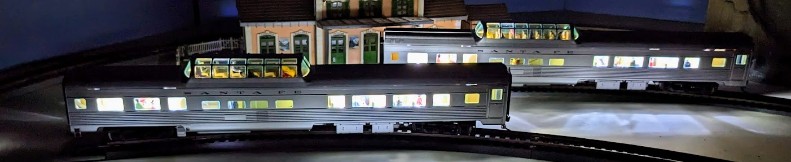
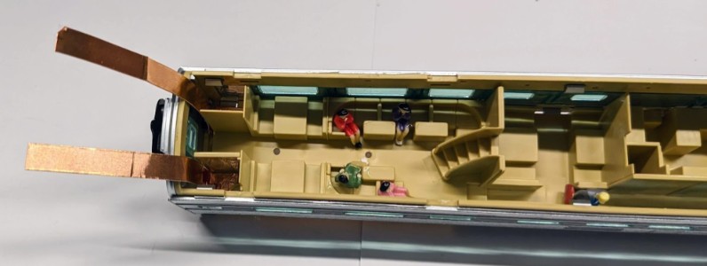
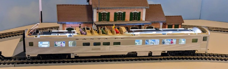
In this post, we’ll see how to add lighting to that specific dome car, the 85’ Budd Dome Coach Santa Fe (910-30402), to get this result:
Walthers LED Kits
On that product’s web page, there is a “LED Interior Lighting Kit” link at the bottom that sends us to https://goo.gl/cGuZib which is part 910-220. Since this is the "recommended" kit, Allen got these kits and I showed him how to install that in his Walthers Mainline 910-30002 85' Budd Large-Window Coach Santa Fe (910-30002). The kit is a bit finicky in the way the metal tabs need to be installed on each end to power the LED PCB, but with enough motivation we were able to make it work, and for all purposes, it works as intended and documented.
Then he moved on to the Mainline Dome Coach part 910-30402 and we found the recommended LED lighting kit did not work at all.
The first problem is that the Mainline LED kit 910-220 is composed of one single long LED PCB which cannot be installed due to the elevated dome passenger compartment. It's not even long enough for that car!
The LED kit 910-220 provides a long flat PCB that doesn’t fit on this car with the observation area in the middle.
All the little characters were added by Allen previously.
The second problem is that the Mainline LED kit 910-220 provides metal tabs that need to be installed at each end to bring power from the bottom trucks to the top LED PCB, but in case of the dome car the end is filled with the interior shell so there's no space to install the electrical contacts.
Allen noticed that Walthers offers a different LED kit for dome cars:
"Walthers Proto 920-1061 Passenger Car Interior LED DC / DCC Lighting Kit"
So Allen got that but then it doesn't fit either. Only later did we realize it's a Proto and not a Mainline kit.
After checking with Walther’s excellent product support team, they confirmed that indeed it’s a mistake in the listing and the Mainline LED kit 910-220 is not compatible with the 85’ Budd Dome Coach Santa Fe (910-30402).
However, after looking at all these kits, I realized we can “kitbash” something fairly easily. So that’s what I’m going to explain here.
Parts
We’ll use the following parts:
- 1x Walthers Mainline 85’ Budd Dome Coach Santa Fe (910-30402).
- 1x Walthers Mainline 910-220 Budd Passenger Car LED Interior Lighting Kit (aka “the Mainline LED kit”).
- 1x Walthers Proto 920-1061 Passenger Car Interior LED DC / DCC Lighting Kit (aka “the Proto LED kit”).
- 1x Conductive Adhesive Copper Foil tape in 6 mm width.
This one is described as being 0.1mm thick.
Make sure that the adhesive part is clearly described as conductive too. That’s important. - A basic multimeter with a continuity detector feature.
Principle of Operation
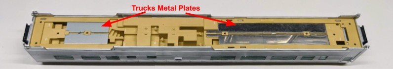
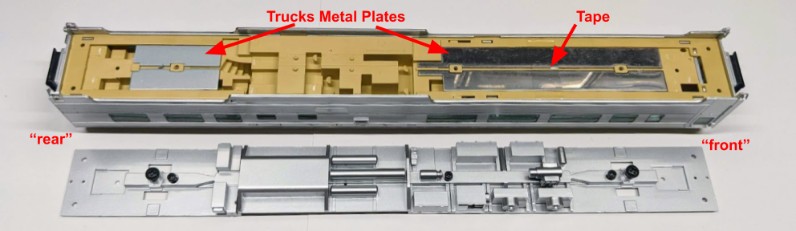
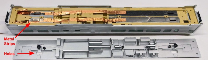
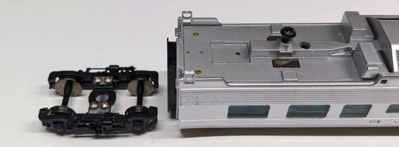
The non-dome cars in this series (the 910-30002 Budd Large-Window Coach Santa Fe) have two separate metal plates at the bottom of the car, under the interior flooring. These two bars serve as weights, and they double as power pickup for the conductive trucks. The associated Mainline LED kit 910-220 provides two metal strips that connect to these bars and provide power to the LED bar located in the roof.
In the dome cars, we can’t do that. For starters, there are four metal plates at the bottom -- two per truck, and they are not connected together. Then we don’t have space on the end vestibule to place the kit’s metal strip that would “lift” the power to the LED bar.
We have almost all the elements we need, yet we need a way to bridge them to have power continuity. Some folks may be able to solder something, however I don’t feel that there’s enough clearance to fit even small wires, and my soldering skills are not good at soldering thin wire to metal plates.
If I can’t provide connectivity via wires, what can I do instead? Options I can immediately think of are conductive paint and conductive tape. These are sometimes used to do simple electric circuits. In this case, I went for thin copper foil tape: it’s relatively cheap, it’s conductive, it’s easy to apply, and being adhesive it will neatly stay in place.
Here’s how that's going to work: we use conductive tape to connect both trucks to each other, and then we use the conductive tape to bring power to the LED bar at the top of the car. This is the overall schematic:
Overall Schematic: we use conductive tape to connect both trucks to each other,
and then we use the conductive tape to bring power to the LED bar at the top of the car.
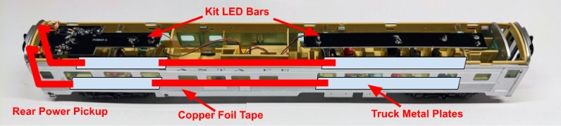
Note: I refer to the left of that schema as the “rear of the car”. That makes the vestibule with the doors the “front” of the car, it matches Santa Fe pictures I’ve seen online, and it matches the seat orientation in the elevated observation area.
Here’s the high-level overview of the operation:
- Disassemble the Budd Dome Coach (top, bottom, and part of the interior).
- Use the conductive tape to pick up power from the two trucks and bring it up to the LED kit on the roof.
- Use the conductive trucks and body-mounted couplers from the Mainline LED kit 910-220.
- Use the 2-parts LED bar from the Proto LED kit 920-1061.
Each step will be described below in detail.
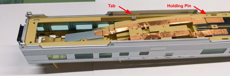
Opening the Budd Dome Coach
We’ll need access to the interior, so first we need to remove the roof. There are a lot of guides online that describe how to do that: hold the car with two hands, twist it back and forth a few times, and the roof tabs’ tend to release. It’s a bit conceptually nerve-wracking but actually that’s not hard, and seems easier than the notice that comes with the car (which suggests to use a x-acto knife to push the tabs). Note that it’s enough to get all the tabs released on one side, then it’s easy to access the other tabs and release them.
With both hands, hold both sides of the car as shown (only one hand pictured here because I needed to hold the camera, but imagine the other hand on the other side) and twist in opposite directions. This pops out the retaining tabs.
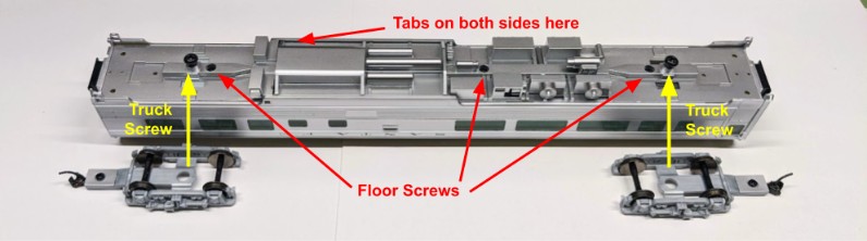
Removing the bottom part:
- Remove the trucks by removing their main holding screw. I typically place the screw back on the bottom body.
- Remove the 3 smaller screws that hold the bottom to the interior seats. You can put the screws back on the plate to avoid losing them.
- Gently pull on the sides. There are only 2 tabs holding the bottom piece.
When I did the first car, I removed the entire floor/seating interior part. That made it easier to put the conductive tape. I did not remove the interior walls. The floor/seating interior is held in place by a little horizontal pin and a vertical pin in the middle, which makes it tricky as the middle part of the interior needs to be both lifted and pulled sideways, with each pin counteracting the other one. It was a pain to remove, and it was a pain to reinstall later. The good news is that we don’t need to remove that entirely -- below we’ll lift the “rear” part of the interior just enough to apply our tape.
Applying the Conductive Tape
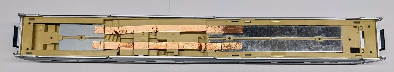
First I used some conductive tape to bridge the front and rear truck plates:
Some important details:
- Do not bridge the left/right sides. We want the left and right sides to be electrically isolated from each other. If you electrically connect both sides together, the car will short your layout!
- The copper foil is very thin. I cannot stress that enough. When applying it, it tends to crease easily, so apply moderate tension and smooth it out as you apply it.
- Don’t remove the entirety of the paper backing. Cut a piece of foil to the desired length, peel a little bit of the backing off on one side, apply it, and peel the rest as you go along. Otherwise, because it’s very thin, the foil tends to curl and glue to itself and ends up like a tangled ball of shiny copper mess.
- Because it’s very thin, it also can break very easily, especially since we are following some fairly sharp edges. If the copper foil breaks, either remove it and apply new one, or cover it with another piece to ensure electrical continuity.
- When reassembling the first car, the long plates kept falling so I held them in place with some kapton polyimide tape. That’s because I stupidly removed the transparent tape that was there from the factory. So don’t do that! Keep it, as it prevents these metal bars from falling in the first place.
- Do not apply any oily substance to the copper foil. I’ve put a drop of CRC 2-26 contact cleaner on it thinking it would improve conductivity, only to realize later that the copper foil tape would not adhere anymore to itself due to the oily substance.
Once the tape is applied, use the multimeter in continuity mode. We want to have continuity between the front and rear plate on each side, but not between the left and right sides.
That was the easy part. It’s a good intro to learn how to deal with the copper foil tape.
Now we’ll add some more tape to bring our circuit to the rear of the interior, and wrap around the floor. Here are the steps.
First we push the rear of the floor. There’s a little tab to go through midway. The floor/seating interior is held by a pin in the middle. I suggest not bother removing it.
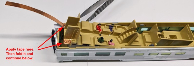
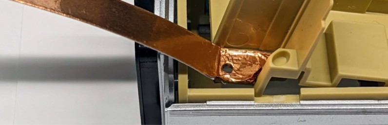
Next, cut a piece of copper foil, and stick it at the top on the very rear part of the interior. Remove only what you need of the backing paper. Once that’s in place, fold the tape underneath and connect it to the rear metal plates, as such:
We fold the tape around because we’re going to connect to it from the top in the next step.
Tip: Ensure the rear metal plates are fully covered, as shown above. It seems to greatly improve power pickup -- later the metal strip wipers from the truck will contact directly with the copper foil, rather than the rear metal plate which seems to have poor conductivity.
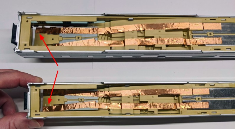
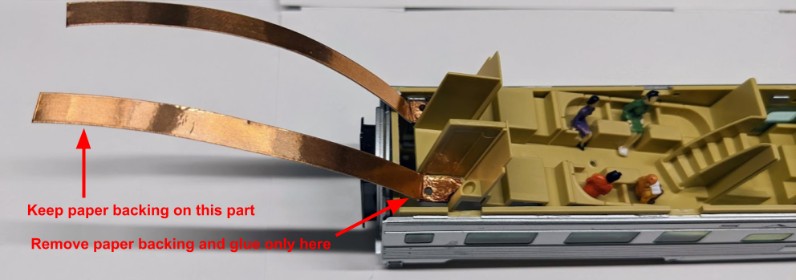
The next part is a bit more tricky… I’ve done this part 3 times (on two different cars) and each time found an easier way to do this. So here’s the last installment: cut a piece of copper foil as shown below, cut off a few millimeters of the backing paper on one side and stick it over the tape that we previously folded around the end of the interior. Do not remove the rest of the backing paper.
Here’s an important detail: we just covered a through-hole in the plastic interior, which will be used later to screw parts of the coupler. So we’re going to clear that hole. To do this I punch the hole with an x-acto knife or a small screw driver and then I clear the hold with something round (screw driver, pliers, toothpick). Should look like this:
Here’s what this looks like once we push the interior in place::
This is a good time to perform a continuity check with the multimeter.
Now it’s time to install the silver bottom plate back --it has screws that hold the interior in place, and pulling the interior down will help the copper foil make contact with the vertical strips we just installed.
There are 4 metal strips to install, and they must fit through the holes in the bottom plate.
All my attempts at vaguely placing the metal strips, then putting the bottom plate and aligning the metal strips have failed. Instead I found an alternative: put a tiny amount of white glue on the bottom plate to hold the metal strips while we fit it back on the car:
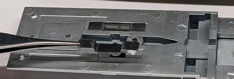
The end result should look something like that:
On that picture the truck is upside down, to show the screws that will make contact on the protruding metal strips.
This point is a good time to do yet another continuity check with the multimeter. We should have continuity between the front and rear protruding metal strips, but not between the left and right sides. We should also still have continuity to the vertical copper foil tape we left hanging around previously.
Finally we can install the 2-segment light bar from the Proto Kit:
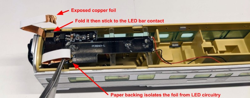
I remove a few mm of the paper backing from the “vertical” copper foil, fold it, and make it stick to the corresponding contact on the Proto LED bar.
Keep the rest of the paper backing in place -- it prevents the copper foil from making contact with the rest of the LED bar circuitry.
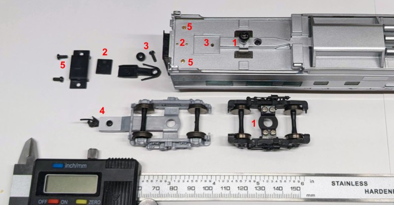
Install the Body-Mounted Couplers
For that part, we’ll follow the instructions provided in the Mainline LED kit 910-220. They do a good job describing it. To be honest I had to read the instructions 3 times before I could make sense of them because I wasn’t familiar with the vocabulary used. So I made my own instructions:
Instructions for myself:
- Remove the truck. Keep the screw on.
- That little square plate goes at the edge with the two little horizontal holes. It’s called a “swinging drawbar pad” in the instruction sheet.
- Thread the longer screw through the washer and then through the “swinging drawbar” (the piece with whiskers), then screw this in place. If installed correctly, the little whiskers bump against the plastic indentations and the drawbar self-centers itself, which is very entertaining.
- Take the original coupler and copper centering spring from the original truck and place it on the drawbar. It’s a bit finicky because there’s nothing holding it in place at that point.
- Place the longer plastic piece, the “drawbar brace cover”, on top of the coupler and attach it using the two medium screws. Note that there’s a ledge on the plastic, and that ledge goes towards the outside. I find it useful to put light pressure on the “cover” to keep the coupler from falling off. Once screwed in place, verify the coupler can swing freely.
- Finally place the new trucks in place (see below), with the screws in contact with the metal strips protruding from the car’s bottom (the truck is shown upside down in the picture… the little screws should run against the metal strips on the car).
Tips:
- It really helps to carefully read the instructions fully first, and examine each piece to see where each one goes.
- There are 3 screw sizes in the kit; I use the caliper to get a rough idea of which one is which. For each coupler we need one longer screw (M2x5), and two of the medium ones (M2x4). We don’t use the very tiny screws.
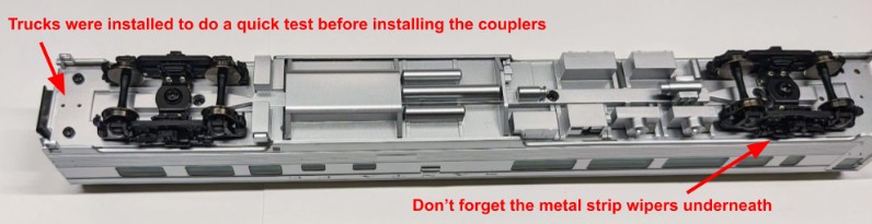
Install Power-pickup Trucks
We just use the trucks that came with the Mainline LED kit 910-220. Simply reuse the screw from the original silver truck, place the new black trucks in place, and voilà!
Things to watch out for: the little screws that make electrical contact must of course be touching the metal strips installed in the bottom plate of the car’s body. Needless to say, in my trial-and-error, I managed once to install both trucks and totally forgot to install the metal strip wipers… Only did I get a clue when electrical contact was not being made.
In the dome car product listing, I notice that the trucks are oriented with the brake cylinders towards the outside.
At this point, we’ll do yet another quick continuity check. Power should be continuous from each trucks’ side to the LED bar, however there should be no continuity between the right and left sides of the trucks. If there is, something’s wrong!
If the continuity check looks fine, now’s a good time to put the car on the track. The LED bar should turn on!
Order of operation: it’s easy to install the trucks before mounting the couplers just to see the LED bar lighting with the car on the test track… but if you do that, remember you’ll need to remove the truck to install the couplers anyway. It’s only one quick screw so it’s no big deal.
Finally we can snap the roof back in place, right? Wrong! First we’re going to put it on the track and verify it still lights up, and that installing the couplers and trucks has not messed up anything.
Once that’s validated, we can put the roof back in place. Note the orientation of the roof.
Tip: double check you’ve placed back the upper observation seating area before closing the roof!
Conclusion
I hope this guide will be helpful for anyone who tries to do the same lighting conversion. There was some trial-and-error in the process, and in the end I basically redid some of these steps 2 or 3 times on both cars because I’d keep forgetting one step or mess something up. On the other hand, that led me to find an easier way to perform some steps. It’s well worth it, the results are really nice. I also go to experiment with copper foil tape and found that worked really well for this project.