Distant Signal |
2025-03
Distant Signal is a CircuitPython script for an ESP32 to display the state of a remote model-railroad turnout on a LED Matrix Display. A small custom language allows one to define the panel display, and then animate it with a simple trigger. The color and animation script can be loaded from an MQTT broker.
[Video] Distant Signal deployed at the Randall Museum
Source: https://github.com/model-railroad/distant-signal
License: MIT License
Origin of this Project
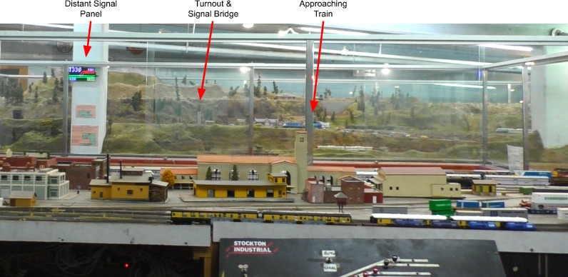
The design of the Randall Museum Model Railroad makes it so that we cannot easily see the state of the turnouts on the mainline from the main operator’s control panel. We have two main tracks coming out of the yard and merging into a single track on the mainline. Although there’s a signal bridge, it’s about 20 feet away and impossible to see its LED indicators properly. Besides, when we operate during Saturdays, there’s a lot of public just standing in the way.
Thus the idea is to have a display mounted high enough that we can see it from far away, like this:
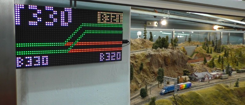
With a glance at the Distance Signal panel, we can quickly verify that the turnout is properly aligned. The panel also indicates the block occupancy around the turnout:
How it Works
Distant Signal is just a “dumb” display panel -- the panel does not know anything about the model railroad.
The implementation is based around having a JSON file defining a series of layers that represent blocks or turnout, with the ability to show/hide these layers. Control is done indirectly via MQTT.
The panel subscribes to specific MQTT topics on the MQTT broker. To update the panel, a server simply needs to publish messages on the desired MQTT topics.
Example Usages
Distant Signal has been designed to primarily display different turnout states, and layer block states on top of that.
However we’re not limited to just displaying turnout information. The implementation treats states as individual “layers”, of which only one is displayed at a time, and which content is a series of lines, rectangles, and text. Thus we can display a few different things. Blocks, on the other hand, are individual elements that can be toggled on/off individually.
Basic usage, as shown in script_example.json: A single turnout is shown.
- 2 possible states are possible: “normal” (a.k.a turnout straight) vs “reverse” (a.k.a. turnout thrown).
- 3 blocks are shown -- one for each leg of the turnout.
Extended usage with a siding track:
- In this case we want to display 2 turnouts, and 4 blocks.
- There are 4 possible states for the turnouts (both normal, both reverse, normal/reverse, reverse/normal).
- 4 blocks -- 2 for the main vs siding, plus the mainline outside the turnouts.
Dave Kaufman suggested we can also use this as train signage to indicate a train is approaching a station, indicate a train is loading freight for example, or returning to a yard. In the context of the Randall Museum where the model railroad is controlled by an automation computer, we can easily use either block sensors or the automation program to display messages other than just turnout states.
Hardware used for this project
- AdaFruit MatrixPortal CircuitPython ESP32-S3
- AdaFruit 64x32 RGB LED Matrix - 4mm pitch or equivalent.
The script is fairly customizable.
There are many more LED Matrix displays compatible with the AdaFruit MatrixPortal platform that should work.
ESP32 Setup
Instructions for the MatrixPortal ESP32-S3. This page has the specification, pin out and this page explains how to connect the LED Matrix display.
- I power the Matrix Portal S3 with a 5V 4A USB-C power supply, as recommended. However that seems a tad overkill as I have measured the display to consume only between 1A and 2A. Note that these displays only update 1 or 2 rows of pixels at a time and power usage only depends on the current lines being updated, not the entire display.
- The device should already come with a USB bootloader and create a USB drive visible under Windows or Linux. If needed follow the instructions to reflash the bootloader.
- Plug the ESP32, click the reset button, and as the onboard LED becomes purple, immediately click the reset button again. If you do it right, the onboard LED should stay and remain green. A drive named QTPYS2BOOT should appear on USB.
- Run the setup/_get_circuitpy_uf2.sh script and drop the downloaded uf2 file on the USB drive. Once the device reboot, a USB drive named CIRCUITPY should appear.
- Uploading the code on the ESP32 is done by copying files to the USB drive named CIRCUITPY. You can drag'n'drop stuff manually. I prefer to automate things using scripts with MSYS, Cygwin, or Git Bash.
- Tip: Open src/_lib_upload.sh and src/_upload.sh.
Change the line D="/d /f /cygdrive/f" at the beginning to add the drive letter needed for your USB drive. For example "F:" is "/f" under MSYS, "/cygdrive/f" under Cygwin, or "/media/usb" under Linux.
I run these from the Terminal tab in VS Code:
cd src # upload all libraries (once) ./_lib_upload.sh adafruit_logging ./_lib_upload.sh adafruit_connection_manager ./_lib_upload.sh adafruit_requests ./_lib_upload.sh adafruit_ticks ./_lib_upload.sh adafruit_minimqtt ./_lib_upload.sh adafruit_haslib ./_lib_upload.sh adafruit_matrixportal ./_lib_upload.sh adafruit_bitmap_font ./_lib_upload.sh adafruit_display_text ./_lib_upload.sh neopixel # upload the fonts, images, and default script (once) cp ../font/tom-thumb.bdf /circuitpydrive/ cp ../font/tom-thumb2.bdf /circuitpydrive/ cp wifi_off.bmp /circuitpydrive/ cp wifi_on.bmp /circuitpydrive/ # upload source code (after each modification) ./_upload.sh |
Update settings:
- Open setup\settings.toml.
- Open F:\settings.toml (or whatever is your CIRCUITPY USB Drive)
- Copy the settings to the USB drive file, and modify as needed to set the SSID/password for your wifi and your MQTT server information:
# Setting these variables will automatically connect board to WiFi on boot CIRCUITPY_WIFI_SSID="Your WiFi SSID Here" CIRCUITPY_WIFI_PASSWORD="Your WiFi Password Here" # MQTT integration. MQTT_BROKER_IP="" MQTT_BROKER_PORT=1883 MQTT_USERNAME="username" MQTT_PASSWORD="password" MQTT_TOPIC_ROOT="ambiance" # DistantSignal Configuration for this panel MQTT_TURNOUT="Your_Panel_MQTT_ID_Here" |
Development and Debugging
To monitor the serial out of the AdaFruit MatrixPortal S3, configure VS Code Serial Monitor with Text mode, Port USB, Baud rate 115200, Line ending LF.
Note that whilst the ESP32 resets (after pressing the "reset" button), VS Code disconnects from the USB port and loses valuable debug information. Thus you can't debug your script if it fails to load this way. Instead, the easiest way to debug a broken script is to upload it. Any upload triggers a soft reboot which reloads the Python VM and exposes any missing imports:
cd src ./_upload.sh |
MQTT Interaction
These are the topics that Distant Signal subscribes to.
Update Configuration Script
Topic: "distantsignal/%(T)s/script"
Value: JSON stringified.
Where T is MQTT_TURNOUT as defined in setting.toml.
This defines the main configuration script for the display panel. See next section for syntax.
Set Turnout State
Topic: "turnout/%(T)s/state"
Value: string
Where T is MQTT_TURNOUT as defined in setting.toml.
This selects one of the names defined in the states section of the configuration script.
Set Block State
Topic: "block/%(B)s/state"
Value: "active" or "inactive"
Where B is the one of the names defined in the blocks section of the configuration script.
This selects the state of a given block number. Blocks are hidden until they are set as either actie or inactive.
Configuration Script Syntax
See script_example.json and script_parser.py for a quick overview.
JSON structure
The script is encoded in a JSON structure as follows:
- At the top level, a dictionary with keys “settings”, "title", "blocks", and "states" is expected.
- At the inner level, we encode graphics primitives for drawing lines, rectangles, polygons, and text, which is called a "drawing instruction list".
- “settings”:
- x/y coordinates of a “connecting” message displayed before we get a status from the MQTT broker.
- “cnx-lost-state”: the name of the state to display when the connection is lost. The suffix “:no-blocks” can be used to indicate that the blocks layer should not be shown.
- “init-state”: The name of the state to display when the panel is loading. The suffix “:no-blocks” can be used to indicate that the blocks layer should not be shown.
- Title: the "title" entry is a single drawing instruction list (see below).
- The title is optional.
- If present, it is always drawn first (bottom z order).
- States: the "states" entry is a dictionary of named states, each with their own drawing instruction list.
- The states key is optional, or it can be empty.
- States are drawn after (above) the title.
- Distant Signal will then select one state to draw. All others are ignored.
- For example, a panel representing a turnout would typically have 2 states: "normal" and "thrown" (or "reverse"), and may define an additional error state. Only one of these states can be selected and drawn at the same time.
- Blocks: the "blocks" entry is a dictionary of named blocks.
- Each block must have 2 inner keys: "active" and "inactive". Each one is a drawing instruction list.
- Blocks are drawn after (above) the current state.
- For each block defined, Distant Signal will keep an active / inactive status (matching a block being empty or occupied).
- If the current state name has the special suffix ":no-blocks", the blocks are not drawn. This is useful for example for an initial state (no configuration known) or an error state.
- For example, we would name the error state "error:no-blocks".
Drawing Instruction List
A drawing instruction list is a mini-programming language with 5 instructions that can contain the following commands:
- Text:
- {"op": "text", "x": INT|STR, "y": INT|STR, "t": "TEXT", "rgb": "#RRGGBB", "scale": [1|2], "font": [1|2]}
- x and y can be either a number or a simple string expression with numbers and + and - operations (e.g. "64-26+5").
- Negative numbers are interpreted as offsets from the left/bottom size of the screen.
- "font" and "scale" are optional. When missing, they evaluate to 1.
- Rect (filled):
- {"op": "rect", "x": INT|STR, "y": INT|STR, "w": INT|STR, "h": INT|STR, "rgb": "#RRGGBB"}
- x, y, w, and h can be either a number or a simple string expression with numbers and + and - operations (e.g. "64-26+5").
- Negative numbers for x and y are interpreted as offsets from the left/bottom size of the screen.
- Line:
- {"op": "line", "x1": INT|STR, "y1": INT|STR, "x2": INT|STR, "y2": INT|STR, "rgb": "#RRGGBB"}
- x1, y1, x2, and y2 can be either a number or a simple string expression with numbers and + and - operations (e.g. "64-26+5").
- Negative numbers for x and y are interpreted as offsets from the left/bottom size of the screen.
- Due to the underlying library used, lines are always 2 pixels in width.
- Polygon (filled, 3 points or more):
- {"op": "line", pts: [ { "x": INT|STR, "y": INT|STR } * 3+ ], "rgb": "#RRGGBB"}
- pts is a list of { "x": INT|STR, "y": INT|STR }.
- x, and y can be either a number or a simple string expression with numbers and + and - operations (e.g. "64-26+5").
- Negative numbers for x and y are interpreted as offsets from the left/bottom size of the screen.
- There must be at least 3 points, expressed in a consistent perimeter order.
- The polygon is automatically closed.
- The underlying library seems to reasonably handle concave polygons.
- Template:
- {"tmpl": "TEMPLATE_NAME", "vars" : { "VAR1": "VALUE1", ... }, "x": INT|STR, "y": INT|STR}
- A template injects a top-level drawing instruction list in-place an optional x/y offset and an optional value replacement.
- A top-level key is expected that matches the TEMPLATE_NAME.
- The key used for the template name must be unique.
- That value must be a drawing instruction list.
- Any instruction key matching one of the "vars" keys is replaced by the corresponding value before processing.
- x, and y are offsets applied to the template drawing instructions.
- x, and y can be either a number or a simple string expression with numbers, variables, and + and - operations (e.g. "64-26+5+VAR").
- Templates can include other templates; however they should not call back into themselves (infinite loop). CircuitPython has a very short call stack size; attempts to embed too many levels of templates are likely to crash the python interpreter.
- script_example.json shows templates in action: they are used to define the common look for all active and inactive blocks (using the top-level “block_active” and “block_inactive” template names). Within the template, the text command uses “NAME” as a variable for the block name. The templates are then used in the block list where the “NAME” variable is given the proper block codename (e.g. “B320”) and the desired location.
- Comments:
- {"#": "anything here"}
- Since JSON does not allow for comments, an instruction with a key "#" is interpreted as a comment and its content ignored.
- Note: in the current implementation, any unknown instruction is ignored (e.g. lacking an "op" key or with an invalid operand for "op"). This may be changed later.
Table of contents:
Hardware used for this project
~~
~~