H0-Scale Model Layout Test Track #2 |
2015-08
I have a small "layout" at home, which is actually just a glorified test track.
This describes how I designed and built the second iteration of it.
Goals
Typically, people create a train layout to either focus on scenery or run trains and the goal is often to be as realistic as possible -- what is called "prototypal" in the jargon.
You can find plenty of amazingly realistic scenery in magazines and myriads of guides on how to achieve that. There's also an excellent video on TrainMastersTV which explains why having the largest layout around isn't always a good idea. Start small, "less is more" as the old saying says. Well, this is my version of "the least that provides the most" to me.
When I start on a project, I make it a habit of identifying the goals and, most important, the non-goals.
My goal was to have a test track and a place to experiment with a variety of things. Examples include:
- A place to experiment with Arduino-based electronics and automation. This is my core motivation.
- Trying new decoders, matching locomotive speeds. The essence of a test track.
- Occasionally run a train to make sure it behaves properly before I bring it to the train club.
But more importantly, what are my non-goals? Non-goals are where you draw the line, what you do not want to end up doing. If you don't know your limits, how can you reach them? Here where my non-goals:
- I do not focus on the realistic aspect of a model train layout at home: I don't run prototype, I don't build extensive scenery. That's what train clubs are best for, in my opinion. I don't want to build a masterpiece that nobody but me will see.
- I do not want a simple vanilla plywood board. It has to be somewhat better than that.
- I don't need a lot of staging. Cars and engines will go in and out of a box as needed.
- I'm not spending 10 years or even 2 years finishing the layout and the scenery. A week top is all I need.
In my view, trains are toys and the layout is a toy in itself, which is then used to play with other toys. Must go deeper…
Consequently defining constraints and designing something that fits within the constraints was a core part of the project by itself. These are the constraints I defined:
- The working space I have is rather limited, in this case a 4"x10" rectangular area.
- How to fit 2 ovals in the allocated surface and still have an elevation track?
- Very often layouts are either pretty bare -- trains merely running on top of plywood -- or with extensive scenery. Could I figure something in between and give it more of a "toy" appearance?
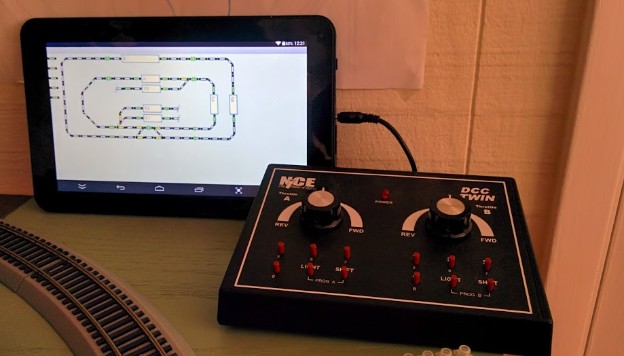
- Use arduinos to perform turnouts control and train controls. That will be discussed in another article.
- My main motivation was to play with automation so building the layout had to be fairly quick yet give something that is not too shabby.
- As an additional constraint, my plan was to change the layout in maybe a year or two.
Reading
Preliminary reading: if you ever want to design a layout, even a not serious one, grab a copy of Track Planning for Realistic Operation: Prototype Railroad Concepts for Your Model Railroad by John Armstrong.
Your local library probably has it and you can find many copies on Amazon or eBay. The book is simply fantastic and explains tons of things on how to design something beyond the obvious oval track.
It's targeted towards the serious layout construction and the findings will apply to any scale and any kind of layout.
Design
After some deliberation, I opted to use Bachmann EZ-Track segments rather than laying out flex track. It did add quite a few constraints on the design that can be achieved. For the small amount of track required here, the cost difference wasn't much since I already had some track around. The only issue with EZ-Track is the #4 turnouts with an 18" radius. These are a typical cause of derailment.
The main argument against it is looks. The old black plastic EZ-Track is simply awful. The newer gray with nickel-silver is somewhat better, but not as good looking as the Atlas one.
One obvious issue with the EZ-Track is that it severely limits what can be designed by the fixed curve shapes and the fixed segments lengths. For example a switching yard would be much more compact using Atlas #4 turnouts than the EZ-Track ones.
The main argument for it was I already had some around from a previous toy train set so that did seriously reduce the cost. The layout design is going to be short lived and redesigned the next year (which I did and the flexibility actually encouraged me to not worry and just try different arrangements… it's easy to go back if needed; I would have not done that with a more typical roadbed & track setup).
I designed the layout using SCARM, which is was an excellent free paid software with a limited trial that I recommend for planning (I no longer recommend it because the author decided to change his licensing model from free to paid software, which is a lame bait-and-switch technique). Although it’s fairly solid, it’s not without fault and consequently it doesn’t shine as much face to the competition as it used to be when free. The obvious other choices are AnyRail (commercial, limited trial). and XTrkCAD (free as in open source, but terrible UX wise). An important issue I had with SCARM is there are small variations in size in the Atlas and EZ-Track track components that do add up so it's only good for early prototyping and not to get a precise track measurement. After lots of a variations, I finally settled on this design:
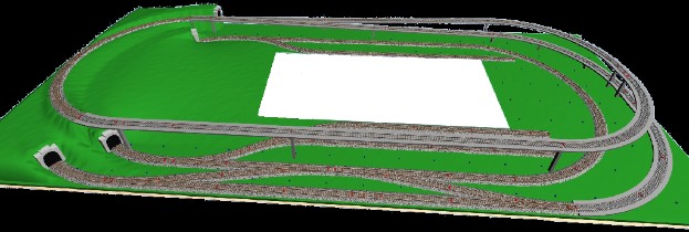
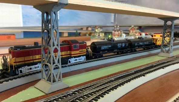
The design is a double oval where the outside oval is an eight-figure that loops over itself using an elevated track and two small tunnels. There are 2 service areas, one with one track and the other with 2 tracks. The elevated track has 5 inches of clearance and features a 2.8% grade in and out. The crossover uses #6 turnouts.
Construction
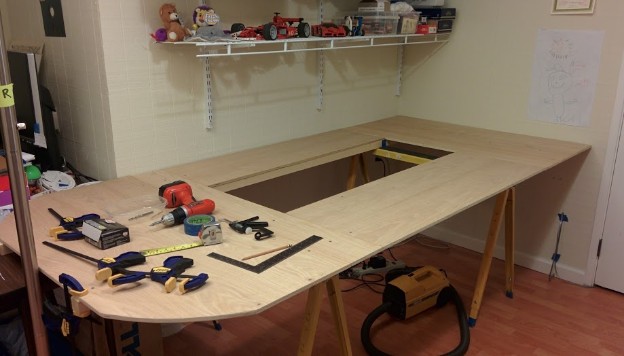
I created a stable base for the layout and laid the track on it to verify that it fit as expected.
I used ½ inch oak plywood sheets which I cut in 1’x4’ at work. There's a simplistic "frame" consisting of 2"x2". The plywood is screwed in place using deck screws. This way it can be rearranged very easily yet it forms a very stable base that does not twist.
Can you spot a potential Inglenook Siding in the design?
One thing I learned from my previous layout is that access holes are important. I can't reasonably reach anything beyond 2 feet.
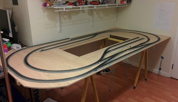
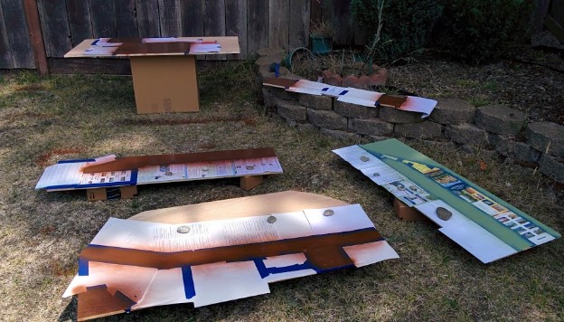
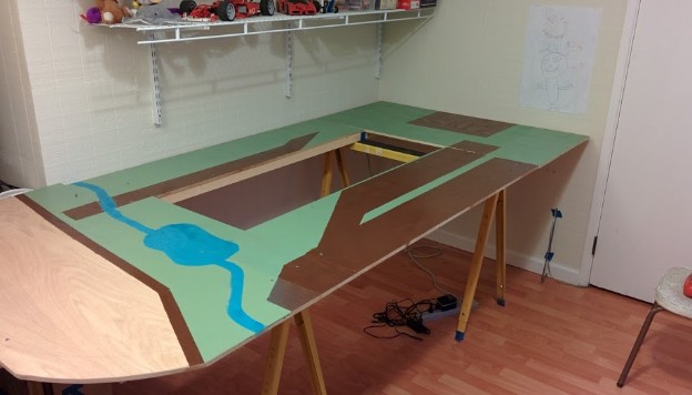
I wanted all that bare plywood hidden away without going into full scenery making. A middle approach was to paint the plywood using basic aerosol paint:
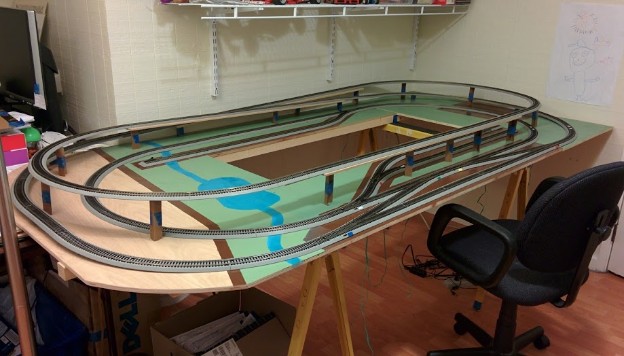
At that point I could put the track back onto it. To double check the elevation I simply cut pieces of cardboard to build some pillars; once that checked out right, I created the ramps using 2"x2" wood blocks and ¼"x3" oak boards:
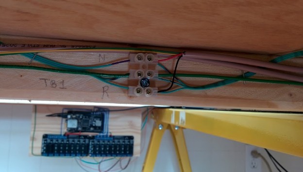
At that point, I checked all the connections with the DCC and wired the snap-style turnouts to my custom arduino setup:
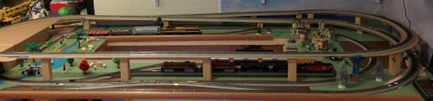
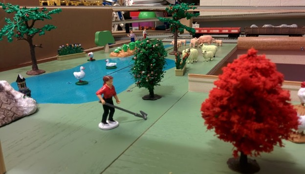
The final step was to enlist the kids to add some much needed "scenery" to the layout:
I also added a backdrop image of sky and clouds that I printed on 32" paper. Technically the backdrop image has a low mountain/hill range yet it is actually hidden by the elevated track, a fact which I failed to realize when I took the photo. I will have to either tear it down or use another photo. Also I did not get the size right and it didn't fully cover the full width and side. Seriously, double fail \o/.
The result was pretty much as I wanted it. It looks engaging yet not "serious," pretty much like a toy.
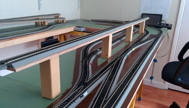
There are only 2 parts left to deal with, scenery wise. The tunnels are right now simply under a basic cardboard setup. Eventually I would like to carve a little mountain out of foam. The elevated track still uses the wood blocks for pillars. I started replacing them by custom-made pillars that I'm creating using a 3D printer and SketchUp:
Update on the Design
One year later I did tear the "layout" down and reworked the design.
I did learn a few things:
- The bridge had a lot of visual appeal, many people who saw the layout thought it was nice that I managed to work it in. It also made the outer loop run twice longer than it could have been overwise.
- However from an operational point of view, the bridge was merely an annoyance.
- It did not add any operational variety, being just a longer loop on the outside.
- When using the layout as a test track for speed matching, the extra length meant I was never using the outer loop.
- It made access to the front yard difficult, often moving or knocking down things in the way.
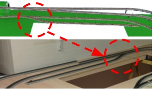
- When I developed my automation using camera detection, the elevated track was obscuring the lower track in places.
Something I knew before and that is good to overstate: The "S" shape caused by two EZ-Track #4 turnouts is most often problematic. This creates problems with the couplers on long engines like modern SD70s and lightweight cars tend to derail due to coupler pressure on the trucks, even at slow speed.
In his Track Planning for Realistic Operation book, John Armstrong explains why the S curve is so problematic and how to solve it, namely by adding at least a straight segment of typical car length between both curves.
The way EZ-Track is setup means that any parallel siding using #4 turnouts will inherently create the dreaded S curve issue. One may note that the old train sets that came with such tracks generally had a pure oval shape with one straight spur going in the inside at an angle, with a single turnout. This inherently avoided the problem.
Another issue I quickly found out was the siding in the back of the layout. If you look at the 3d rendering above, the turnout is on the left but in the final version it is on the right:
The reason is fairly simple. I designed the layout so that trains in the inner loop would turn clockwise, which is the normal way trains run on double-track mainlines in the US. That made the back siding having a leading turnout which meant any engine trying to pull cars in the siding would be stuck in there.
In operations it's actually better to have a trailing turnout -- a train goes past the turnout, throws the switch and then backs up in the siding and this leaves the engine free to uncouple and leave the cars behind. That is also well explained in the Track Planning for Realistic Operation book although I had figured it out earlier since there was no way to automate dropping off and picking up cars otherwise.
I have two remarks about the EZ-Track.
First from a design perspective, I find it very useful for mainline but not so much for yards. The #4 turnout makes it too abrupt and has the inherent S curve issue. Because the angle is too open, it makes track spacing much wider than needed; Since it is less compact, one can fit much less yard track compared to using Atlas #4.5 or #6 turnouts. An hybrid solution would be to use EZ-Track for simple mainline and use Atlas for sidings and yards but in that case why not design the whole thing using Atlas track in the first place…
Second, one thing I do like with EZ-Track is the ease and sturdiness of the connections. I used the newer gray/nickel-silver track instead of the old black/copper track. The rail joiners make very good contact and the plastic tabs hold the track firmly in place. The whole track does not need to be glued or tied down in any way and doesn't move since it's self-rigid. With a small size of 4x9, one track power connector is good enough and there is no need for a power bus, repeated feeders and soldering joints (all of which you'd want for an Atlas or flex track), which considerably makes it easier to install and modify. I also found the nickel-silver makes very good electrical contact and is easy to clean with basic alcohol or white spirit and a small track cleaning car.
Related Links & Pages
- 2018-10-01 - Cameras, OpenCV, and occupancy detectors -- Features of video of automated trains running on the Layout #2 using cameras w/ IR sensors. That video provides a good view of this layout in action.
- 2017-04-10 - Layout #3 “Test Track” -- Discussion on the replacement for Layout #2.
~~
~~