NCE Cab Bus |
2017-2019
The NCE Cab Bus connects peripherals devices such as cabs and sensors to an NCE Command Station.
In this article, we’re going to look at the protocol used by the NCE Cab Bus and how we can use it.
I have two separate goals in mind and we’ll see if they are possible to achieve:
- First I’d like to have an arduino send turnouts commands to my NCE command station via the cab bus.
- DCC accessories such as the Hare control a Tortoise and respond to fascia buttons. However when a turnout is manually switched this way, the command station is unaware that the turnout has changed. The idea here is to have an arduino monitor the turnout state and send corresponding commands to the station to make sure its state reflects reality.
- Second, I’d like to use my own ProCab when JMRI is connected to a non-NCE command station such as DCC++.
- Here the computer running JMRI would drive the NCE cab bus and talk directly to the cabs on the bus.
These are two different requirements. In the first one, we want to create a compliant device that will work with existing NCE command stations. In the second one we want to “simulate” just enough of the protocol used to be able to communicate with a cab.
There are other possibilities of course. For example an interesting application would be to snoop on the cab bus to list which consists have been defined. An Android tablet could be used to easily create consists (by acting as a cab) and display that list. This is useful in a club that has members with NCE Cab06 cabs which lack the ability to create consists directly. That example is a bit weak as it could probably be implemented differently (e.g. by reading the command station memory).
2.1- Communication with the NCE USB Interface
2.2- Communication with the NCE ProCab
3- Experiment: Display NCE cab bus data
1- Physical Layer: RS485
Rather than reinvent the wheel, NCE chose the RS485 specification for their cab bus.
This is clearly documented in their protocol PDF:
https://ncedcc.zendesk.com/hc/en-us/article_attachments/200182749/Cab_bus_protocol.pdf
Without going too much into the details, it’s useful to know what RS485 is (and what it isn’t): it is a serial bus using a twisted pair of wires. Several devices can be connected on the bus at the same time. Only one device can “transmit” (send bytes) on the bus at a time while the other devices “listen” (receive all bytes exchanged).
Note that the RS485 specification is an “electrical” specification for both receivers and senders. In practice that means one can find RS485 driver components that will do all the dirty work of sending or receiving the electrical signals and from a computer point of view we can treat it as a serial port.
From an electrical perspective, the signal is sent in a mirror fashion on two wires. It’s the difference between both that indicates what is a zero or a one. There is no “+” vs “-” wire. Instead they are called A and B.
One thing that RS485 is not is a protocol. This is application dependent. Since only one device can transmit at the time, it’s up to the devices to define how that works and how they synchronize themselves. How the NCE cab bus works in that regards is clearly defined in the PDF above:
- The command station does all the transmitting. Devices mostly listen.
- All the devices have a number between 1 and 63.
- The command station pings them one by one.
- When a device sees its number being pinged it has a very specific window (100 µs and 800 µs) to start transmitting.
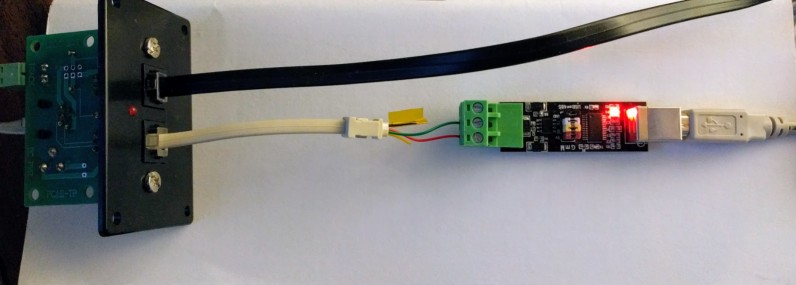
To experiment, I got a cheap RS485-to-USB converter and plugged it on the cab bus using a simple phone plug as adapter: red wire goes to B and green wire goes to A.
Some RS485 specs allegedly inverted A/B in their nomenclature. As a reference point, the NCE USB interface has an NS DS75176 chip on the RS485 port and this is clearly specified in the NCE documentation.
Tip: When reading data of the RS485, most of the traffic comes from the command station and is mostly composed of bytes in the 0x80-0xC0 range. If you get mostly bytes in the 0xF0 range, that means you should invert the A/B connection on the RS485 adapter.
Note: when using an FTDI clone on a Windows computer, be very careful of “FTDIgate”. The proper alternative is to use Linux for all FTDI devices, or even better to use a device with a CP2102 which doesn’t have this problem.
2- The NCE Cab Bus Protocol
NCE description of the cab bus communication protocol:
https://ncedcc.zendesk.com/hc/en-us/article_attachments/200182749/Cab_bus_protocol.pdf
I’ll give a simplified primer here:
- The protocol is entirely driven by the command station.
- Cab bus devices each have an address from 1 up to 63.
- The command station sends a “ping” byte to all the devices numbers. Devices reply when it’s their number.
The command station sends 2 types of bytes:
- Bit 7= 1 / bit 6 = 0 … Bytes range 0x80 .. 0xBF : These are “ping” bytes.
- 0x80 is a ping to “broadcast” address zero. This is used to send the fast clock to all devices.
- 0x81 up to 0xBF is to ping a specific cab bus. Devices have a specific time to reply before the command station pings the next device.
- Bit 7 = 1 / bit 6 = 1 … Bytes range 0xC0 and up: These are “data” bytes sent by the command station.
Devices:
- Always reply with bytes < 0x80, with bit 7 = 0.
- There are “types” of devices: ‘a’, ‘b’, ‘c’, ‘d’, etc.
- Devices reply with either a 2-byte protocol or a 5-byte procol. They can’t change their protocol mid-way.
At that point I’m going to jump directly to some examples. In my case I’m only interested in 2 types of devices: the NCE USB interface and the ProCab handheld controller.
2.1- Communication with the NCE USB Interface
The NCE USB interface is a type ‘c’ device. It always replies with 5 bytes. The 5th byte is an XOR checksum of the previous ones. From what I see, replies have 2 formats:
- addr_high addr_low data_1 data_2 checksum
- “function” addr_low data_1 data_2 checksum
To understand the behavior, it helps a lot to be familiar with the host serial protocol used by the NCE USB interface:
When using it, I have always been mostly interested in 2 commands: 0xA2 to set an engine speed or use a function, and 0xAD to set a DCC accessory (e.g. throw a turnout). There’s a direct relationship between the host format of the NCE USB and what I see on the RS485 cab bus. The only difference is in the leading function byte.
Examples below; the bytes in bold are the same; the bytes in italics represent addresses:
NCE USB protocol |
Cab Bus protocol |
Description |
A2 C2 19 04 13 |
04 19 04 13 0A |
Speed 19 (out of 128) on loco 537 |
A2 C2 19 06 00 |
04 19 06 00 1B |
Stop-forward on loco 537 |
A2 00 0A 06 00 |
4F 0A 06 00 43 |
Stop-forward on loco 10 short addr |
AD 00 30 03 00 |
50 30 03 00 63 |
Close/normal on turnout 48 |
AD 00 30 04 00 |
50 30 04 00 64 |
Throw/reverse on turnout 48 |
AD 00 FA 04 00 |
51 7A 04 00 2F |
Throw/reverse on turnout 250 |
Note that the NCE address range is:
- Short DCC engine address: 1-127
- Long DCC engine address: 128-9999 (0x270F)
- Stationary decoder address: 1-2048 (0x800) on PowerPro, 1-250 (0xFA) on Powercab.
How to compute the loco address:
- On the NCE USB protocol, this is simply the MSB LSB. Add 0xC0 to the MSB for a long address.
- On the Cab Bus protocol:
- Short address is 0x4F + one byte < 0x80 for short address.
- Short range: 4F 01 … 4F 7F
- Long address is 2 bytes: MSB = (address >> 7) ; LSB = (address & 0x7F).
- Long range: 00 01 … 4E 0F
To compute the stationary decoder address:
- On the NCE USB protocol, this is simply the MSB LSB.
- On the Cab Bus protocol:
- MSB = 0x50 + (address >> 7) ; LSB = (address & 0x7F)
Since bit 7 can never be set on data from a device, the bit 7 from the address is on the hi byte.
Obviously the first byte is both an address range and a function selector at the same time.
The notes in the NCE USB PDF indicate the max stationary address and some important characteristics of the NCE USB and command station (e.g. can it read from the CS, can it use the programming track, etc.) as configured using the jumpers on the card. Given the somewhat precarious software on the NCE command stations, I’d be cautious and make sure to respect the documented limitations.
So we can already get an idea of how to create a stationary decoder that would provide feedback about turnouts being thrown to the command station:
- Wait for byte 0x80 at boot as a way to “sync” with the bus.
- Wait for the programmed address of the decoder (1..63 + 0x80).
- The device has between 100 µs and 800 µs to start replying. ⇒ The doc is adamant the CS will not wait any longer than that.
- Reply with 0x50 + (address >> 7) ; address & 0x7F ; (normal = 3 | reverse = 4) ; 0x00 ; xor of the 4 previous bytes.
- Ignore everything else on the bus.
2.2- Communication with the NCE ProCab
The ProCab is a type ‘a’ device, e.g. a dumb terminal with a display.
By “dumb”, it means most of the interaction actually happens on the command station.
The cab receives orders indicating what to print and simply indicates which keys are pressed on the keypad.
Here’s an example of interaction from a command station and ProCab at address 2:
02 to CS: 7E . 7F . CS to 02: D2 . 02 to CS: 61 a CS to 02: C0 . CE N C3 C C5 E E0 E0 E0 E0 E0 02 to CS: 7D . 7F . CS to 02: C2 . C4 D C3 C C3 C E0 D4 T D7 W C9 I CE N CS to 02: C3 . E0 D6 V F1 1 EE . F1 1 F2 2 C1 A E0 CS to 02: C1 . E0 E0 E0 E0 E0 E0 E0 E0 CS to 02: CE . CE . CS to 02: C0 . CC L CF O C3 C FA : E0 F5 5 F0 0 F5 5 CS to 02: C2 . C6 F D7 W C4 D FA : E0 F0 0 F0 0 F0 0 CS to 02: C3 . E0 ED - ED - ED - ED - ED - ED - ED - |
Lines in bold are communication from the cab to the command station.
Each byte is shown in hexadecimal without the 0x prefix followed by the corresponding ASCII letter when relevant.
Note: for brevity all numbers below are mostly in hexadecimal without the 0x prefix.
I omit the “pings”, which precede each command station message. That means on the display above:
- The command station sent a 82 ping, to which the cab replied with 7E 7F (request refresh, no speed change). This identifies it as a device that replies using the 2-byte protocol.
- The command station sent a 82 D2… The display above omits the 82 “ping” byte. To this the device replies with 61 (“a”) indicating it’s a type “a” device (a dumb terminal).
The cab repeatedly replies with 7D 7F to pings (no key press, no speed change). There are omitted above except for the first occurence.
The C0..C3 commands indicate literally what to print on the 2x16 display, which is what a ProCab has. Some of it makes sense, and there’s a bit of unclear stuff going on.
The display is 2x16 and is thus cut in four quadrants of 8 characters each: C0 / C1 for line 1 and C2 / C3 for line 2:
C0......C1...... C2......C3------ |
Section C1 is repeatedly overwritten by the fast clock sent by the command station every second.
Although it’s confusingly written, the doc indicates that ASCII 0x20 is encoded as 0xE0, 0x30 is encoded as 0xF0, 0x40 is encoded as 0xC0 and 0x50 is encoded as 0xD0. To convert an NCE “display” byte to ASCII:
- Clear bit 7 : nce & 0x7F
- If bit 5 is set, clear bit 6: if (nce & 0x20 != 0) { nce ^= 0x40 }
Let’s start by the last C0, C2 and C3 lines.
Remember that each byte must have bit 7 (0x80) and bit 6 (0x40) set. So everything will be >= 0xC0.
My cab display looks like this:
LOC: 505 03:40AM FWD: 000 ------- |
LOC: <space> 505 is 4C 4F 43 3A 20 35 30 35 in ASCII which is thus encoded as CC CF C3 FA E0 F5 F0 F5.
FWD: <space> 000 is 46 57 44 3A 20 30 30 30 in ASCII which is thus encoded as C6 D7 FA E0 F0 F0 F0.
So these display the Loco number and the speed on the left of the display: C0 is the top left quadrant and C2 is the lower left quadrant. Thus C0 followed by CC CF C3 FA E0 F5 F0 F5 prints “LOC: 505” and C2 followed by C6 D7 FA E0 F0 F0 F0 prints “FWD: 000”.
On the top right (C0) we have the fast clock. This is cleared by the line C1 E0 E0 E0 E0 E0 E0 E0 E0 which simply prints 8 spaces there. The fast clock is actually regularly broadcasted by the command station after ping to address zero.
Finally the lower right (C1) has the function indicators on the ProCab. All the functions are turned off so we get a space (20 aka E0) followed by 7 dashes (2D aka ED).
The command CE is to set the cursor off. For some reason it’s repeated twice.
The first C3 command that reads E0 D6 F1 EE F1 F2 C1 E0 decodes to <space> 1.12A <space> and is some kind of version number that displays temporarily when plugging the cab.
The first 2 commands are now easier to understand:
C0 CE C3 C5 E0 E0 E0 E0 E0 decodes to C0 (top left quadrant) + 4E 43 45 (NCE) + 5 spaces.
C2 C4 C3 C3 E0 D4 D7 C9 CE decodes to C2 (lower left quadrant) + 44 43 43 (DCC) space 54 57 49 4E (TWIN), which is the NCE name and my command station name (DCC Twin).
And now you can realize something interesting: the display is going to vary based on the command station.
Interestingly the product name and the D2 (query cab type) are only sent by the command station the first time I plug the cab. After it goes directly to the screen refresh.
Second realization: the command station “remembers” the last cab seen (by number). When using a wired cab in a walk-around-the-layout mode, the cab just needs to send a 7E (refresh screen) command to get its screen initialized. All the cab’s state is memorized by the command station. (Anecdote: I’ve noticed when I bring my ProCab at the club and keep on using the same cab address as last time, the cab by default displays the last engine I used, in the same function states… that’s why: the command station keeps the cab’s state even when turned off, unless explicitly cleared.)
Now that we have the basis for how this works in one direction, how does it work in the other direction? For example let’s say I want to be able to create a device that throws a turnout. What does the ProCab do for that? Here’s the exchange to throw turnout 330 in reverse:
02 to CS: 4E . 7F . CS to 02: C0 . C3 C CF O CE N D4 T D2 R CF O CC L E0 02 to CS: 7D . 7F . CS to 02: C2 . C1 A C3 C C3 C E0 CE N D5 U CD M C2 B CS to 02: C3 . C5 E D2 R FA : E0 E0 F0 0 F0 0 F1 1 CS to 02: C8 . CC . CS to 02: CF . 02 to CS: 53 . 7F . CS to 02: C3 . C5 E D2 R FA : E0 E0 E0 E0 E0 02 to CS: 7D . 7F . CS to 02: C8 . CC . CS to 02: CA . F3 3 CS to 02: CA . F3 3 02 to CS: 53 . 7F . 02 to CS: 7D . 7F . CS to 02: CA . F0 0 02 to CS: 50 . 7F . 02 to CS: 7D . 7F . CS to 02: CE . 02 to CS: 40 . 7F . CS to 02: C0 . C1 A C3 C C3 C FA : E0 F3 3 F3 3 F0 0 02 to CS: 7D . 7F . CS to 02: C2 . C1 A C3 C C3 C E0 CE N D5 U CD M C2 B CS to 02: C3 . C5 E D2 R FA : E0 E0 E0 E0 E0 CS to 02: C0 . C1 A C3 C C3 C FA : E0 F3 3 F3 3 F0 0 CS to 02: C2 . F1 1 FD = CE N E8 ( CF O CE N E9 ) E0 CS to 02: C3 . F2 2 FD = D2 R E8 ( CF O C6 F C6 F E9 ) 02 to CS: 52 . 7F . CS to 02: CE . 02 to CS: 7D . 7F . CS to 02: C0 . CC L CF O C3 C FA : E0 F5 5 F0 0 F5 5 CS to 02: C2 . C6 F D7 W C4 D FA : E0 F0 0 F0 0 F0 0 CS to 02: C3 . E0 ED - ED - ED - ED - ED - ED - ED - |
So first we get 4E from the cab, which is the “Select Accy” key.
The command station prints “CONTROL”, “ACC NUMBER: 001”, C8 to move the cursor and CF to enable it.
As I’m typing the number 330, the cab sends key presses (53 53 50) and 40 for enter and later 52 as I select 2 (reverse).
In return, for every keypress, the command station sends screen updates for the lower quadrant (“ER: spaces”) followed by C8/CA to move the cursor and print a single char as I type.
Then there’s a selection screen “1=N (ON) 2=R(OFF)” which is specific to this command station. A PowerPro would have a different answer since it would show the current turnout state.
Finally there’s a screen refresh to print the Loco / Speed / Functions.
There’s a bit of a realization here:
- This is what we call a “dumb device” in computer terminology. In other words the ProCab does literally nothing else than display what the command station asks to print and just send keypress codes. The entire interaction & flow to throw the turnout is handled by the command station.
- Similarly, a consist setup is entirely done by the command station. The cab simply sends key presses and updates the display.
- When using the Shift key to enter e.g. F10-F19 mode, the cab sends “FA” and it’s the command station that displays the F10-F19 and F20-F28 and then keeps track of the state of the cab. The cab then merely reports that a key 0-9 is pressed, it’s the command station which interprets it as a F10-F28.
3- Experiment: Display NCE cab bus data
I wrote a simple python script that listens to the cab bus and displays the data. That’s where the printouts from above are taken from.
Script is available here:
https://github.com/model-railroad/layout-wifi/blob/main/experimental/nce_listen_to_cs.py
To use it:
- Get an USB-to-RS485 adapter. Plenty to choose from on Amazon / eBay. The one I used has an FTDI chip. It’s the most common type.
- The script is made to run on Linux.
- It uses /dev/usb/ftdi and ncurses.
- Running on Linux means you will avoid any potential “FTDIgate” issue as there is no way you can know whether the ftdi chip on the adapter is legit or not.
- Get an old phone “handset cord” (RJ22 / 4P4C) and cut the end (I used the short part of an old DSL filter).
- Connect red/green to A/B terminals on the RS485 adapter. You don’t need the ground.
- Connect the RJ22 to an NCE UTP.
- See picture above for connection.
- If you get bytes mostly in the 0xF0 range, reverse the A/B connection.
- Run the script. Change the dev port if needed (it defaults to /dev/usb/ftdi, but that may depend on your udev rules).
- Display is fairly crude.
- A line at the top indicates which device(s) responded to CS pings.
- In the middle it grabs the bytes from whichever devices replies on the bus.
- At the bottom there’s an unfiltered view of the bytes that transit on the bus, both from the CS and from the devices.
4- Arduino and NCE cab bus
I had a few project ideas regarding using an Arduino to simulate NCE cab bus devices. Two ideas I had are these goals I described in the introduction. Eventually I decided to implement them in a completely different way -- e.g. in my case why bother sending data to the NCE Command Station when I can have an Arduino directly send data to the JMRI JSON server, thus bypassing the command station? There are pros and cons for each approach.
That said, if you want to use the NCE cab bus with an Arduino, I’d highly recommend you start with the NceCabBus library and the example sketches provided by https://mrrwa.org/nce-cab-bus-interface/ -- chances are they already do what you want, and you can contribute back to them.
5- Conclusion
I’m just scratching the surface here, although there isn’t much more to it underneath anyway. One thing that I have omitted are the NCE AIU-01 sensor devices. These have their own device type and are out of scope for my initial goals. I don’t have an NCE Mini Panel for testing (my guess is that it probably acts as type ‘c’ like the NCE USB).
Speaking of goals, how do they hold?
The NCE USB protocol (type ‘c’) is suitable to create an arduino-like device that sends turnout commands to the command station. Since a specific timing is required to start transmitting, it would have to be done using e.g. an arduino rather than a computer or Raspberry Pi. However the logic is extremely simple -- wait for one byte matching the device’s cab address and emit 5 bytes with the turnout number, the state and the XOR. So this should be fairly trivial and reliable. The one limitation to remember here is the 63 max addresses on the cab bus.
Simulating a command station to directly interface a cab to JMRI is both easier and harder with a type ‘a’ “dumb cab” device than I expected.
One thing that the bus snooping above shows is the extensive role of the command station in dealing with a ProCab. I really had no idea it was doing literally everything. All the operations whether it’s speed/direction control, momentum, consisting, program key and even handling of the shift-function state is all done by the command station. On one hand it means replicating the exact behavior would be more work than expected, but on the other hand it also means a “virtual command station” does not have to do all of this, and actually doesn’t even have to be any similar at all.
It also means a “virtual command station” would not have any of the NCE “advanced” consisting functionality (i.e. programming CV 19) as this is all done by the command station. However it would be fairly easy to program something similar using soft-consisting, which JMRI can do.
As far as the protocol used itself, there are a few aspects worth point out:
- On “dumb cabs”, there is absolutely no packet checksum.
- There is also no ack feedback from the command station.
I think I need to stress that: as far as network protocols go, this one has no feedback and no checksum mechanism whatsoever. It simply does not account for network errors at all. There is absolutely no way in the protocol for a ProCab to detect that a packet was garbled and ask for it to be retransmitted.
That explains why it’s so frequent on a ProCab to have corrupt displays or that it can be really hard to enter loco numbers if a single byte with a keypress is missed or if a screen refresh command is even slightly garbled, or go entirely unresponsive for several seconds like we notice regularly at Randall -- this has nothing to do with the ProCabs, it’s all about the command station and a protocol that does not take network failures into account.
~~
~~