HO-Scale Model Layout / Test Track #4 |
2020-03

I have a small "layout" at home, which is actually just a glorified test track. It is entirely unfinished, and will never be.
This describes how I designed and built the fourth iteration of it.
I have a page detailing the construction of Layout #2, and this one focuses on the latest version, “Layout #4”.
5- Basic Scenery: No More Pink Foam
6- Basic Scenery: Lighting & Backdrop
7- Basic Scenery: Ground Cover
8- Basic Scenery: Lighting & Guardrails
9- Basic Scenery: More Sky Backdrop
1- Goals
As in many projects, success starts with identifying the scope and goals of the project, and often most importantly what are the non-goals. In this case the main non-goal is that I am not building a “real” model train layout. What I really need is a test track to fine tune engines and a “lab” area to experiment with projects which I often apply later to the Randall Museum Model Railroad. As such, what I need is:
- At least one loop to tune engines.
- A few garage tracks to store a few engines & cars.
- No scenery. I am not even pretending this to be a “real” model train layout.
- Experiment with a modular construction.
- Experiment with track changing over time.
- A fairly limited footprint.
A lot of my model train activity focuses on maintaining the Randall Museum Model Railroad, as can be seen in the blog. As such, pretty much every new electronics module or thing that I prepare or design for the museum is tried at home on the test track first. Thus the “layout” focus is not really on the layout itself; it is an experimentation bed.
2- Design History & Evolution
Layout #2 was mostly based on the “4x8” principle, even though technically it ended up as a 4x9.5 ft size footprint. Two double loops, a little bridge, etc.
What I learned from that:
- The “4x8” form factor was limiting. Four feet is way too large. It takes too much space if placed in the middle of the room, and I cannot reach from one side to another if placed against a corner.
- I tried to mitigate that by using an access hole in the middle, but that means I could not use the place underneath for storage.
- The layout was too low for using when standing up, and I did not like to sit down to operate it as I constantly needed to get up then sit down to do anything.
The bottom line is that I realized I wanted a layout at the same height as my standing workbench, and with a form factor where I could be “in the middle” and reach everywhere.
Eventually Layout #2 was replaced by a Layout #3 which was more or less a L-shaped test track on a workbench structure. It was interesting due to its limited corner footprint, but lacked that essential running loop, which I often need to fine tune engines.
Then in 2018, I saw this really amazing module in the online MRH magazine forum:
http://model-railroad-hobbyist.com/node/30751?page=2#comment-294380
The CSX Ridgecrest Module.
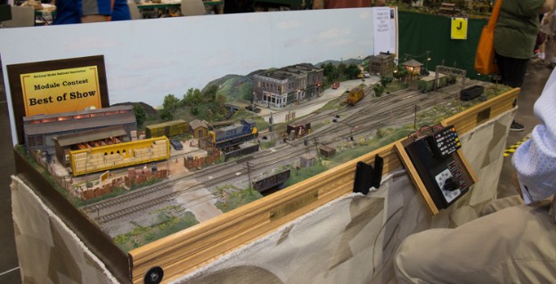
This module was first presented in 2017 in Model Railroader: http://mrr.trains.com/issues/2017/build-a-small-model-railroad
The original plan can be found here: MRR HO scale CSX Ridgecrest.pdf
I really liked that module. I thus decided my design goal would be to have such a module on one side of a layout, then a storage yard on the other side, and connect the two using two track loops, like this:
The yellow track module represents the CSX Ridgecrest track plan, and the blue track module is a storage track.
One idea here was that the right side of the loop was going to be a movable bridge, and the structure would thus form an horizontal U (e.g. ⊃ ).
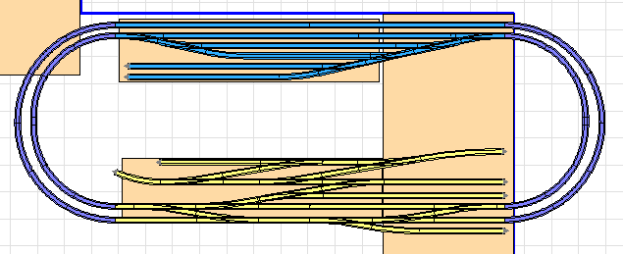
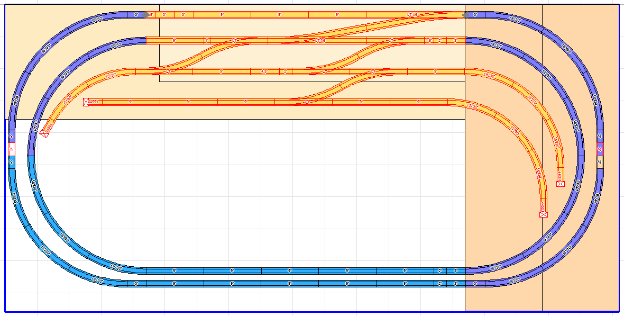
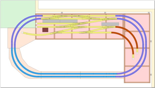
In 2019, I made a lot of iterations on the layout, and I mean a lot. For example at some point I had this design with the two modules with loop track (that somehow changed from double to triple track), but that was a hefty 4x10 ft footprint:
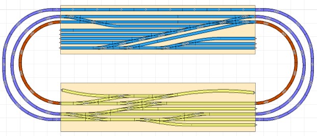
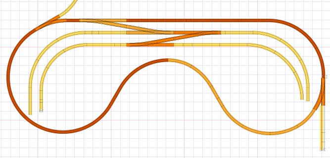
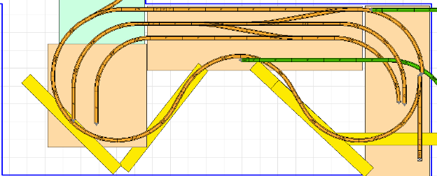
And eventually that got simplified to this, where the blue part at the bottom was going to be an entire curved removable bridge (don’t ask how that even exactly works… where does it go?):
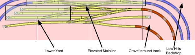
Scenery wise, the design goal at that point was something like this:
Note that at that point I was doing a detailed design of the switching module to decide which turnout and track brand to select… but wait I have all that EZ-Track sitting in a box, so why not use that to do a mock test version? That would require simplifying the switching module a lot since the EZ-Track turnouts are way space inefficient…
However I quickly realized I did not have the space for it, and honestly the removable bridge seemed like a hassle. The CSX Ridgecrest module is 2x6 ft but I don’t have that kind of space. I’m allocating 3x8 ft, and the loops take 2 feet on each side.
Thus I decided to use that typical design adage -- keep it simple:
- Drop the double track loop and use a single one.
- Drop the storage yard.
- Reduce the yellow track module to a minimum (2 turnouts and 2 tracks).
- Compress the oval loop into a “dogbone” shape.
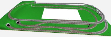
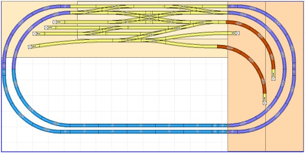
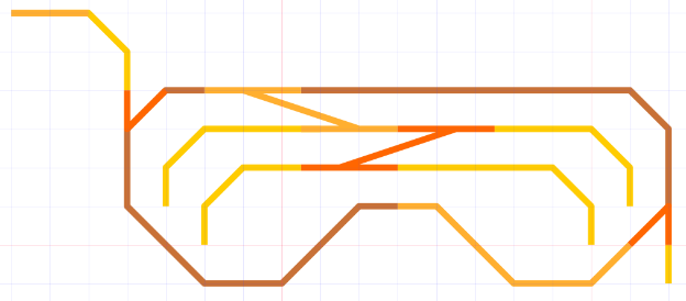
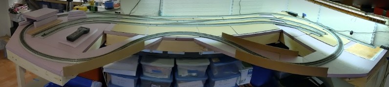
The end result is very different from the starting point. The result is what I call not the “dogbone” shape but the “ski mask” shape:
The track is mostly built using EZ-Track straight segments and 18” radius curves. There’s a bit of cheating where in a couple places I drop it to 15” radius curves. The inner turnouts are the EZ-Track #6 turnouts, and the outer ones are the #4 turnouts.
Note that the tight radius means I won’t run long engines on this, or at least not with cars. For example the Rapido RDC SP #10 can run, or an SD70 engine can run, but their couplers overhang prevent any car from being pulled by these. That’s not really an issue as the only times I expect to run these engines they would run alone, for demonstration or for testing purposes.
I do have small base engines and old era short cars -- my usual D&RGW line up, and these can run fine on these tight radius without any issues.
I originally was going to scenic this, and I wanted to have a little bridge, a little river, and add buildings like on the CSX Ridgecrest module. I however quickly dropped these requirements as honestly these are not so useful for my use at home. I prefer the flexible aspect of the EZ-Track and I have already altered the track in minor ways.
The final “schematized” track plan is the following:
3- Construction
Beginning of 2020, I spent a few months figuring out how I wanted to build the structure.
My previous layout was built using a rigid plywood board on top of a rigid frame surface. Here I wanted something different -- as I pointed out, a whole part of this is experimenting.
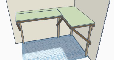
One experiment was to build the layout using a modular frame with foam on top instead of plywood. For storage reasons I also don’t want to have any feet. The modules should hold using a cantilever design or some kind of wall brackets.
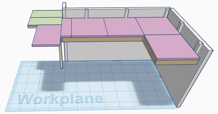
Going back to the original switching module, the frame was going to work like this:
I made two boxes of 2x4 ft size out of wood:
- The side and inner supports of the boxes is 3” x ¾ boards, material is #2 common whitewood from Lowe’s.
- L corner braces are used to hold them together in a square frame open frame.
- L metal brackets are used to support the frames at the desired high on the wall with some plywood in between to provide better load support.
- Covered with 2x2 ft pink Foamular 150 boards.
For the surface, the material is “Closed Cell Extruded Polystyrene” or XPS. EPS may or may not be the same thing (EPS = Expanded, XPS = Extruded… same difference?). The typical choices are Foamular 150 vs 250 where the number represents the compressive strength -- 15 psi vs 25 psi at 10% deflection according to the Owens Corning documents. In the colder Eastern US parts they can get the stuff in 4x8 ft sheets of 2 inch thickness. However in our warner California climate, this is only available in 2x2 ft sheets of 1 inch thickness for the Foamular 150.
It is generally recommended to paint these “pink foam” boards on all sides with a latex paint to avoid moisture absorption (not really a problem here). Oh by the way pink foam is highly flammable and releases toxic chlorine gasses when burning. Just saying… something to be aware of.
The two boxes are lightly secured on the L wall brackets. The original design was to apply scenery and track and then cut the track at the end, allowing the modules to be removed independently. But then after I was done with the modules and had them in place, I decided to drop the scenery and go for EZ-Track, which cannot be cut. OTOH that one is trivial to remove / disassemble and thus requires no cutting, nor gluing.
After I dropped the idea of a removable “front bridge” or whatever it would be called, and instead opted for a “dog bone” (or rather “ski mask”) design, I added one more square module on the left to hold the loop. For that 3rd module, I used 1x4 furring string boards [Lowe’s link] instead of the same wood as before as I wanted to compare the characteristics -- I had never used “furring string boards” before. This was interesting: Fairly light / low density; longitudinally, the boards are fairly straight; transversely, the boards are slightly curved; one side is smooth, one side is very very rough, e.g. unfinished, unsanded. It was however easy to work with and I ended up making the module not entirely square -- the outer lower right section is cut in a slanted manner to avoid having a protruding edge in the middle of the room.
No L-brackets support that 3rd module. It has an actual simple 2x2 leg on one side, and is screwed to the workbench on the other side.
I also decided to create two small bridges for the inner loops, which are the parts in yellow below:
and here’s the actual implementation:
Last but not least… guardrails were added. The modules are fairly high and the track goes very close to the edge, especially on these bridges and that curve on the left. In the initial experiment, I simply cut pieces out of cardboard boxes and used hot glue to fix them to the pink foam. This is supposed to be temporary -- a better looking wood could be used here, but at least I wanted to have something right from the front rather than delay this and regret it once an expensive engine drops to the floor and breaks.
4- What’s Next
At this stage, to make this a “proper” layout, here’s what I could or should do next:
- Paint the module’s wood (in and out, to prevent the wood from warping).
- Paint the pink foam (to hide the obvious pinkiness).
- Add a foam core base.
- Add the final track (e.g. replace the EZ-Track by Atlas / ME / Peco, etc).
- Add a foundation of dirt/grass.
- Ballast the track.
- Add temporary paper structures.
- Add final structures.
At least that was the initial thought. Then I realized that I was not going to do this at first.
Having an “unfinished” track makes it so much easier to alter and change it. Because there’s no scenery, no ballast, no glued track, everything can be modified in a pinch.
I have a ton of ideas to explore, and my interests change over time. And as I had just finished building that experiment, I realized that I was not ready to commit to a final look or scenery. I’m not doing a piece of a show, I’m doing something for me to enjoy, so the first order of business is going to actually use it as is. I don’t care if the guardrails are made of cardboard and there’s pink foam everywhere. But I do care about using it and making sure it is suitable for me. And if it is not, this is the perfect time to change it.
Instead of focusing on the looks & scenery, let’s focus on usability. This is what I have done next:
- Power the 4 turnouts by an NCE Q-Snap. I had never used that before, so it was interesting. I also added support for that in my Android DCC control software.
- Connect the NCE Command Station to the JMRI computer, to have full home control for trains running, trains programming, and turnout control.
- Try out the NCE EB-1 Circuit Breaker. That’s a bit overkill at home, but I use these at Randall and it’s convenient to have a way to replicate testing at home.
- Experiment modifying DCC turnouts with LEDs to directly create direction indicators. I applied that at home before reusing that technique at Randall.
- Temporarily modify one of the loop curves with a surelevation to replicate one derailing condition from Randall.
You may notice a pattern here -- the home layout is a test bed for experimenting, and I often test things at home before I apply them on the Randall Museum Model Railroad.
Another follow up project is to modify an EZ-Track segment to work as a double gap segment with a LED indicator, so that I can isolate one siding as a programming track and make sure the rest of the layout is not connected to the programming track.
5- Basic Scenery: No More Pink Foam
December 2021.
My original intention was to keep the track plan “raw/unfinished”, making it easier to modify it. And I did just that. It’s been a year or more now and I like the track plan. I did some minor tweaks to it, yet nothing outstanding.
At that point, I’m now interested in applying some basic scenery here. Nothing grandiose, however I want a basic change from my pink foam landscape, and I also want to learn some techniques I know nothing about. It’s an adventure! Let’s start simple.
I disassembled the entire layout. It’s easy since the track is just EZ-Track. I took note of how the track was assembled so that I could re-assemble the same way later.
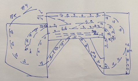
I was also going to update my SCARM schema of the layout then realized it was pointless. Unfortunately SCARM has the same huge limitations: its EZ-Track simulation is not exact and track does not match horizontally, and the major issue is that it lacks any reasonably good print output. When printing a track like this, the track section names are too small to be readable and useful. I just took notes using that hand-made paper version above for immediate reference as it’s easier to read (YMMV on my scribbling obviously).
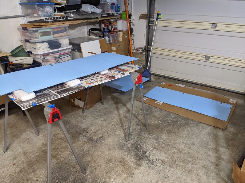
Then I took all the modules frames and their foam out in the garage. I painted the foam on both sides to seal it, and I applied Polycrylic to the wood frame to seal it also (it’s low-VOC, not too smelly, does not yellow the wood, and easier to deal with than polyurethane).
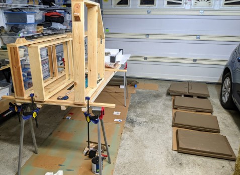
The 3 vertical frames are the wood frames for the 3 modules. I used 2 layers of Polycrylic on that. Unlike regular polyurethane, it doesn’t change the color of the wood at all but more importantly it’s really low-VOC. I still need a mask when applying, but after immediate application it’s quite ok in the garage as the space is well ventilated.
For the foam, I used water-based latex interior paint. Although these are supposedly “low” or “no” odors, they still emit something that I’m somewhat allergic to. Gives me some slight headaches. I left the paint dry a couple days in the garage, and then in the room as I was on vacation away from home. I timed it on purpose to finish all the pain before leaving. When I came back, the paint fumes were no longer a problem.
Reference for self: the color is Valspar 2007-9A Shutter Brown. Originally I was going to choose a lighter tan-like color (more sand-like) and at the last minute I changed to a “wet dark dirt” color because I like the contrast better with the supporting wood frame.
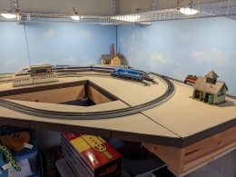
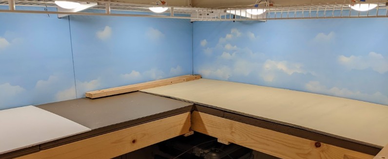
Once reassembled, the base looks better in dark brown than with its original pink color:
Original pink foam |
Painted foam |
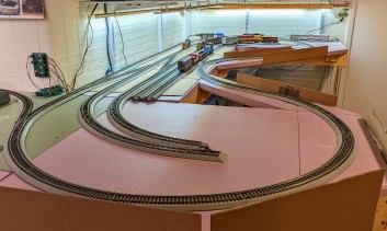
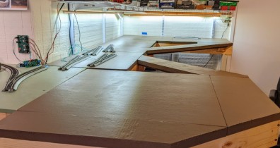
It’s interesting to note the foam paint is interior matte (not glossy) yet it looks shiny when applied on the foam. A test on wood resulted in the expected matte look so really the foam has a direct impact here. Without the camera flash, the color is a lot darker, similar to dark chocolate. That’s a nice improvement over the pink foam.
The next step is that I got some 3/16” foam core board and I’ll use that on top of the foam, to contour the track.
A lot of people apply scenery directly on the foam. However in my case I want to be able to experiment, so I’m going to use foam board as the scenic substrate. If I screw it up, I just trash it and start over. Failure is an option.
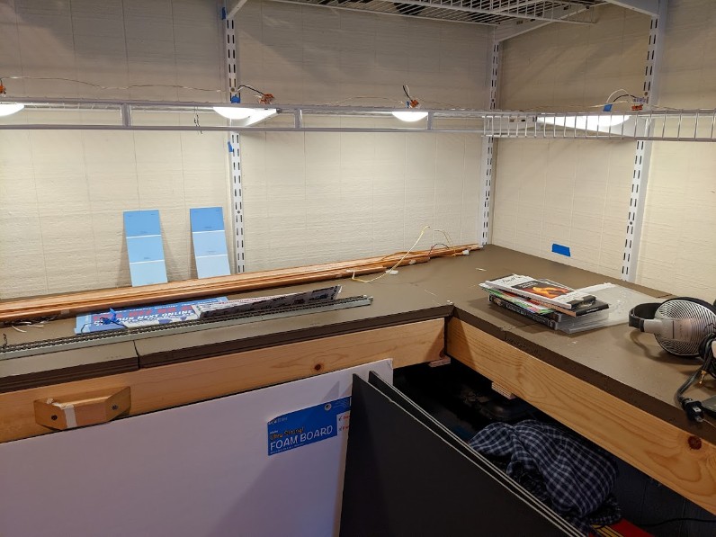
But before that, I want to change my lighting, move that shelf that is right above the layout, and I want to create a backdrop. Got a few ideas to experiment with. More on this later.
6- Basic Scenery: Lighting & Backdrop
October 2022.
Lighting
I changed my lighting from a 12 V powered LED strip to some small round LED ceiling lights in Warm White 3000-3500K. The lights come in a pack of 6, and I temporarily attached them to the shelf above the layout using blue painters tape. I will likely 3d-print some more appropriate fixation supports later.
The original LED strip was a Neutral White 4000K and it turned out to be a bit too harsh for my usage.
One thing that I did well however is on the power side:
This gives me 12 V DC power for the LED strip then for the RV LED ceiling lights, all mounted in parallel. I measured 1.3 amps @ 12 V usage max, and they are fully dimmable. I’m fairly happy with that result. This is a prototype. I’m going to use this for a while as-is before I finalize it.
Once I had the lighting under control, it was time to look into the backdrop.
Backdrop
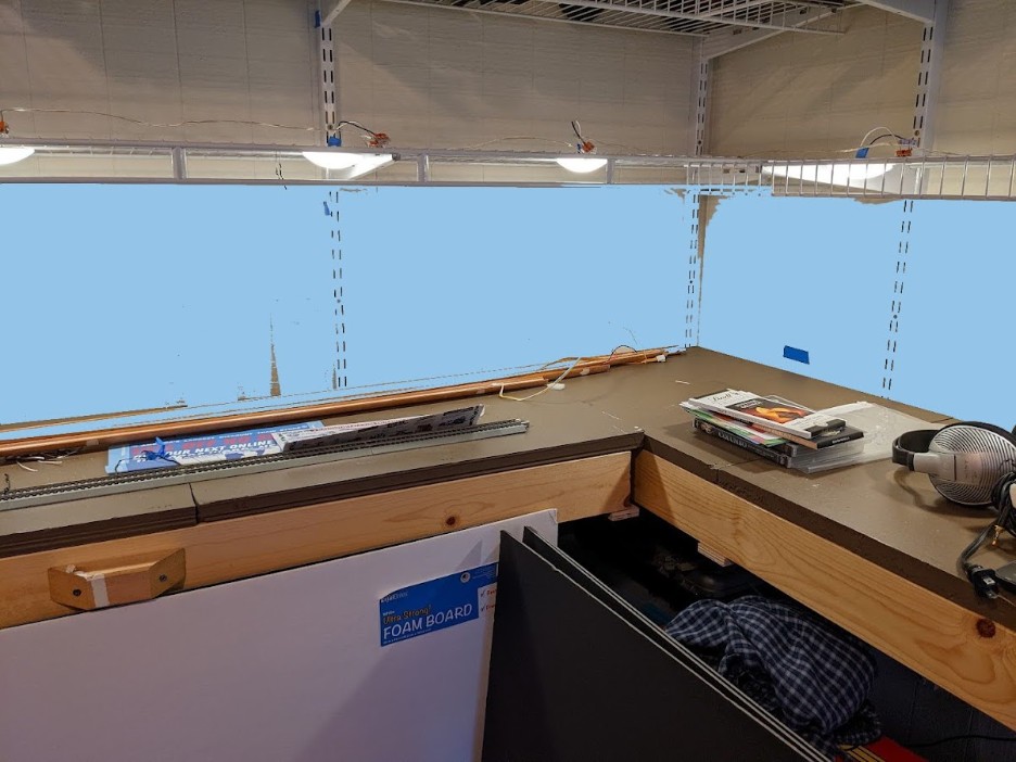
Typical layout design is to paint the walls blue. I did not want to paint directly on the walls, and anyway I have the shelf supports in the way, so a backdrop would have to be something in front of it.
My plan B for the backdrop was commercial backdrops. I found some nice ones on SceniKing and on Train Junkies. But first I wanted to try a DIY approach using a method I’ve seen on TrainMasterTV, and I’d try the commercial ones if my DIY approach didn’t look like I wanted.
The backdrop is going to consist of foam core boards painted. I used 30x40 boards from Staples, which interestingly are present in the store but not at all in their online catalog.
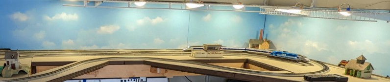
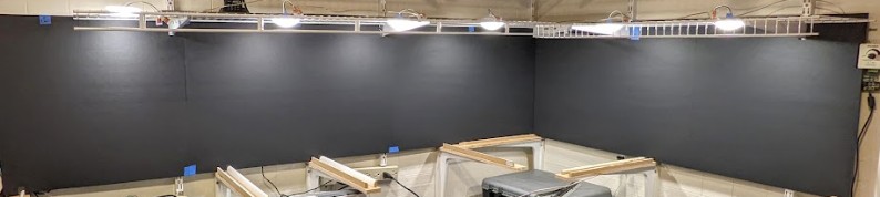
The boards are painted blue and the little clouds are white spray paint. I did not bother drawing hills or anything fancy. Just taped the boards to the wall. I did not want to paint directly on the walls. That's low key, minimal materials, and yet it instantly looks better.
Let’s look at the end result and then back track to how I got there:
To give credit where due, the overall technique I used is derived from the one described by Miles Hale in this video from TrainMastersTV:
https://trainmasters.tv/programs/back-to-the-basement?cid=384610&permalink=back-to-the-basement-p1
The suggested blue color is Sherwin Williams 1792 Bonnet Blue. I’ve seen the same reference in an older Model Railroader magazine, but that’s not in the SW catalog anymore. However we can use a first web site to find the original color RGB value, which in this case is RGB 141 198 228, HEX #8DC6E4, LRV 51.63%, and then we can use another web site to find matching colors:
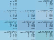
From that we find that SW 6957 Undercool or SW 9049 Sky Fall are suitable matches.
Next is a trip to my local Lowe’s to find color chips. SW 9049 Sky Fall was one of the options I found. I grabbed a couple color chips, and placed them on the future spot, and took a picture of that. Then in Paint.Net I used the color picker tool to color the wall of the desired color to see what it would look like on a picture with the final lighting. That last part is very important. The colors depend a lot on the lighting so it’s important to get that one right first.
I also grabbed an online image of the Rio Grande area, and compared it to my picture. Basically I want to double check that if I take a picture of the layout, it will look like what I expect it to.
Next step was to get 30x40 foam core panels from Staples. Originally I wanted to use white panels, but these are not available right now, so I got the black ones. I cut them and make sure they would fit on the desired location:
That took some back and forth figuring how to cut the panels and make then fit behind the shelf without having to remove the shelf. These foam core panels feature a paper backing on both sides. I did a quick test on a spare part painting on the paper vs removing the paper and painting the foam. The result was a much smoother look when painting directly onto the paper so I decided to keep it. I used some tacky white glue to glue the paper in some corners as it had a tendency to peel off.
Painting these is a bit tricky. I use latex interior matte paint from the store, which is water-based. The panels tend to curl when painted. The solution to this is to paint them on both sides right away -- not even waiting for one side to dry before starting on the other one -- such that the curling negates itself. Once the paint dries, the panels are mostly flat, yet not as flat as their unpainted counterparts. Also, since we are painting paper with a water-based paint, the first coat should be as light as possible. Once the first paint coat is dry, it insulates the paper backing from further moisture, and I thus applied a second coat only on the visible side.
As usual with paint, it looks darker when wet, and dries a bit lighter. Once I had the panels dry, I test fit them in place.
Notice how the junction between some of the panels is quite visible. The two panels on the left and the two most right ones are glued together with a strip of foam core in the back, so at least I wanted these to have no visible edge. An easy workaround was to use some “DAP lightweight spackling” filler I had around. This stuff is neat. Apply a minimal amount of it to fill the gap, then sand it with 200 grit once dry, and paint it over.
Not shown above: when test-fitting the panels, I marked what would be the “ground” level with some blue painters tape. Anything below would not be visible, and clouds would have to be above that “ground level” mark.
Now it was time to paint the clouds. I didn’t take any picture of that part. I used the technique described by Miles Hale in the TrainMasters TV video:
- Take a letter-sized cardboard stock and rip it in two to make some “cloud template”.
- Get a spray can Krylon matte white paint.
- Practiced on a throw-away piece of cardboard how to very very lightly add the clouds in, layering multiple layers.
- The lower part of the panel represents the “ground” level, and things are hazy at the horizon. Thus clouds there must be a lot lighter than the ones at the top, and because they are farther away they should have smaller details.
- At the end, do a quick horizontal pass with the spray to add a very light uniform white haze on the lower part. It represents the horizon being more hazy and less blue. It has to be very subtle -- but then later once dry, I put a piece of the original blue color next to it and the contrast is quite discernable.
One issue I encountered is that my spray paint tended to splatter and leave little white dots around. I worked around that by using a dry-brushing technique using the original blue latex paint to hide the little white dots. Then it was time to test fit the panels again:

7- Basic Scenery: Ground Cover
Similar to the backdrop, I don’t want to apply ground cover directly on the base “pink” foam. That’s because I want to be able to experiment with various things, and maybe fail. The foam top modules were pretty intensive and time consuming to make.
Since painted foam core panels worked well for the backdrop, I’m going to experiment with using foam core panels for the ground cover. The foam core panels are a substrate:
- They are going to be painted with a “sand” color.
- And on top of that some artificial turf will be applied.
The first order of business is to get the end look I want to achieve. I picked up a reference picture:
Desert landscape from https://www.sceniking.com/hos.php
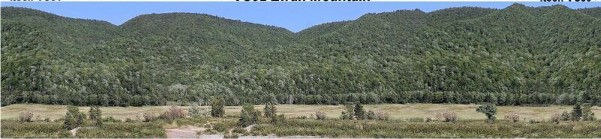
The reference is a wallpaper image from SceniKing (one of my plan B choices). It’s a good presentation for a California or Rio Grande landscape. Note that actual images from New Mexico Rio Grande show a more reddish soil. I want something more neutral and more “sand” color which I believe would be a bit more passe-partout.
On average, the RGB color for the “dirt” on that picture is 214 203 173 #D6CBAD / HSV 43 19 83.
Using https://www.easyrgb.com/en/match.php, I determined a set of matching color I could get around here:

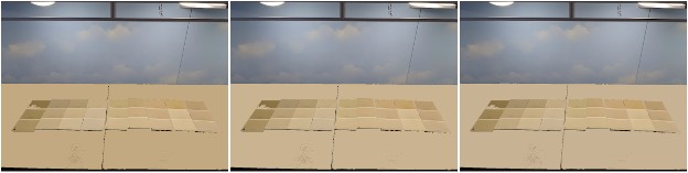
I went to Lowe’s and picked up a number of color paint chips that seemed close enough to that, then used Paint.Net to colorize the surface accordingly. I also explored a few color variations that were not my original choice yet looked good at the store. The problem with store lighting is that it can give a different feel, so it was important to try the color chips at home using my local layout lighting:
Left: Tres Naturale. // Middle: Believable Buff // Right: Netsuke -- the original choices.
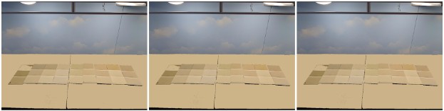
Left: Macadamia // Middle: Softer Tan // Right: Oyster Bar -- the alternate choices.
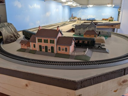
I finally settled on SW 6142 Macadamia as the best candidate. It’s just a tad darker than the original and I feel it will work nicely. I painted one board and tried it in place, and was very pleased with the result:
After cutting and painting the other boards, here’s the result with some track and a couple structures on it:
The next step is going to be adding some ground cover. Before I do that, I’m going to let this sit as-is for a little while whilst I figure out what structures I want, and where.
I also need to finish fixing that lighting, and I want to put back some guardrails in the front. I think I’ll use the black foam board for that again.
8- Basic Scenery: Lighting & Guardrails
November 2022.
Guardrails
Nothing is more irritating than a delicate HO-size train engine or car falling to the ground by mistake after a derailment, or because someone’s sleeve got in the way. I’ve heard countless “I’m not clumsy, that will never happen”. Well I’m clumsy and I admit it. As the saying goes, “hope is not a strategy, it is the only strategy” -- which really translates into Eisenhower’s quote “plans are worthless but planning is everything”.
Thus even on a basic layout like this, I want some kind of guardrails.
There are a few ways to do guardrails on layout. On a fancy scenicked one, a good strategy is to not have the track too close to the edge, add a little hill, and even plant some bushes or trees. Not only is it more photogenic, but it effectively stops any trains.
I’m not going there for this layout as this is really a simple “test track” and I expect I’ll change something in maybe 5 years. My goal is also to have something right now that I can replace later if needed. Foam core board has worked well to do the backdrop and the ground support, so I’ll be using the same material. With this in mind, I ended up with this:
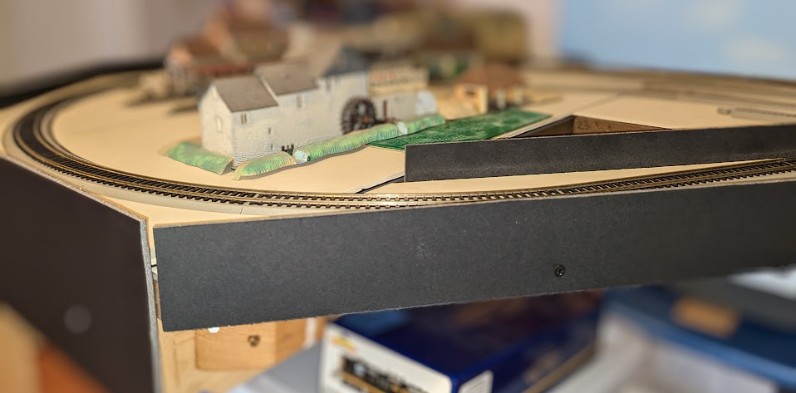
In a previous iteration, I had simply cut out some pieces from shipping card boxes and used hot glue to stick them to the pink foam. That held very well. Here I wanted something a bit more pretty, and that unpainted black foam core board looks good for the task. To secure it, I want something I can replace easily so I opted for screws rather than hot glue. I have screws on the wood fascia side. For the bridge, I tried drywall screws directly in the pink foam, however I’m afraid that’s not going to hold enough so I also added a few points of white glue. I may iterate on this later, yet that will do it for now, and I can move on.
Lighting
For the lighting, I’ve been satisfied with my prototype so it’s now time to finalize it.
What I use is:
- Zitrades Power Pack 48w 12V/4A
- Zitrades DC 12 V Dimming Controller For LED Lights
- Round “dome” LED ceiling lights in Warm White 3000-3500K.
The little dome lights are really nice. The color is exactly what I was looking for, and I like it after a few weeks. 6 lights did not provide the coverage I wanted so I got another pack, and I’ll have one light every foot.
One issue I have is how to fix them. I have a wire shelf just above the layout. I don’t want to glue the lights or use anything permanent. But more importantly, I want the top of the shelf to be flat, as it will be used to store train boxes. So nothing I do should protrude on the “usable” part of the shelf.
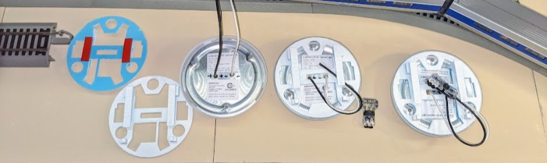
After many (many!) iterations, the solution I came up with is 3d-print a custom-made support that clips to the wire shelf. The recessed lights come with screws but these would protrude on top, so instead I’m using double-side tape to hold the support to the light, and then the support clips on the wire shelf.
Tinkercad of the support:
https://www.tinkercad.com/things/0mBUd8k0nYi?sharecode=jaFA9teZRsyJDQdLsJHEtnPR8-K-r-ktSn7eE67NKiA

The light assembly, from left to right: the 3d-printed support, painted in white on one side; then the dome light itself is taped to the support; finally a T-tap connector connects to the lead wires.
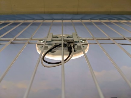
For power, I have a line of 22 AWG wire creating a “12V DC bus” along the center of the shelf, and each light taps into that using a low-voltage T-tap connector.
The light clipped to the shelf, with the T-tap connector connected to the 12 V bus wire.
The entire assembly is flush with the top of the wire shelf.
The first shelf completed.

Between each shelf, I’m using quick-disconnect Wago connectors. This will make it easier to adjust shelves independently if I ever need to.
After having completed one of the two shelves, the end result is as expected and will provide a lot of illumination. Note that in the image above I’m running the dimming controller at around 30%. That’s ideal; LEDs lights have a better longevity when not run to their max specs as they can run cooler.
Edit: The LED dimmer has a switching frequency of around 600 Hz. It makes a notably banding impact when taking videos. I have to remember to set the dimmer to 90% or 100% to avoid that banding when taking videos.
9- Basic Scenery: More Sky Backdrop
December 2022.
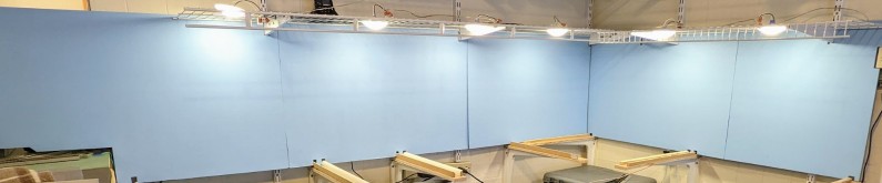
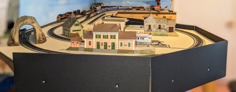
I completed the backdrop on the other end of the layout, around Module 3. This one is not against a wall -- it’s an “isle” that protrudes in the middle of the room. This helps make it more photogenic when filming videos or taking pictures. On the other hand it should not get in the way of continuing working on the layout.
After considering multiple options, I ended up with a multi-panel configuration like this:
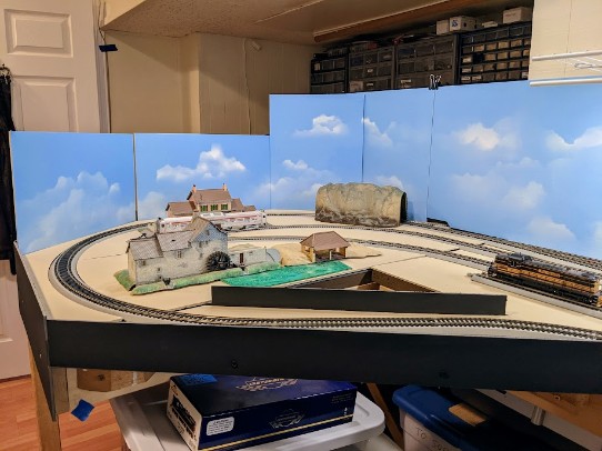
This hides the workbench and the door. The clouds work fairly well here.
The two segments on the left on that picture are held with 2 screws each so they are easy to remove, but they are only held on the side of the workbench and thus not in the way of any scenery.
The segments on the right hold in place using blue painters tape in the back, and these on the other hand, rest on the “sandy” ground foam board so I will have to be able to remove them when I work on scenery or track.
~~
~~